Amsat 3-Helix Feed

  • the idea to build this feed was triggered by Peter, DB2OS in January 20, when he sent me some papers and calculations from Karl, DJ4ZC, to construct a QO-100 feed with 3 helix antennas around the LNB. Additional information came from Achim, DH2VA and Michael, DD5ER, who sent me dimensions for the antenne coupler and Mario who did final adjustments on the Amsat Helix antennas in Bochum.


    Building a feed with three helix antennas is a complex project, so it took three month, until April 20, to get the first feed up and running.


    The goal was to get best reception and not to shade the LNB, and to get the same good TX performance of a single helix feed.


    To measure the shading of the LNB I built the reflector and LNB only, without helix, measured the transponder noise and DATV-MER and then glued three dummy helix on the reflector and repeated the measurement.

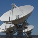
    this is the reflector + LNB, with three dummy helix.


    Resulting transponder noise: a single helix costs about 1.5 - 2 dB. The three helix antennas cost only 0.5 dB. Also MER was about 1dB better.


    My first idea to simply paralleling three helix antennas was impossible, because I never measured the 140 ohms as stated in Wikipedia or Rothammel. Therefore I tuned each helix to 50 ohms and built an antenna coupler.


    2.4 GHz coupler made from brass pipes, inner diameter 20mm.


    Today the new 3-helix feed went into operation. It give the same good TX performance as my single helix feed, and the good RX signal of an unshaded patch feed. The only downside is that it's a lot of work, and a good workshop is needed to build all the components.


    the 3-helix feed in operation


    50 ohms match and holder made from polypropylen


    tuning at the the coupler input with all three helix antennas connected


    vy 73, Kurt, DJ0ABR


    • Official Post

    Why did you not use only 2 helix?
    Did someone try 2 or 4 short yagi with H/V orientation and 90° phasing?


    The aim was to find an optimal solution and probably easy to build feed system with one of the usual LNBs with a diameter of approx. 60mm in the middle and with the 2.4 GHz uplink antenna arranged around it in such a way that it does not interfere or is even disturbed by the LNB. Another important point is that this feed has its phase centre at about the height of the LNB horn.


    You can get about the right gain with 4 cross dipoles or with 4 full wave dipoles in front of a reflector, but the dimensions are very critical. Small deviations of the dipoles or the matching elements among each other cause large phase errors, which can destroy the pattern very quickly.


    To improve the pattern, Karl DJ4ZC came up with the idea to arrange 3 instead of 2 short helix antennas in a triangle around the LNB horn. This construction reduces the ellipticity and illuminates the mirror optimally. These helix antennas need only two or three turns to achieve the right gain.


    The triple arrangement also has the advantage that a helix can be arranged above the LNB. Then the other two helix antennas are on the right and left side of the feed arm, which does not interfere mechanically and therefore no feeedarm modification of the antenna is necessary.


    Instead of the helix antennas you could also use three patch antennas, as Mirek Kasal OK2AQ already demonstrated.

    see: Patch Array Antenna from OK2AQ

    But since these antennas have a high Q and are therefore very narrowbanded, you have again the same critical feeding situation as with the dipoles or even much worse. Appropriate safe construction based on a printed circuit board made of high quality RF material exceeds the costs for most users.


    Anyhow, a lot of thanks to Kurt for this excellent work and first working prototype, a proof of Karl DJ4ZC's concept!


    73s Peter

  • Useful explanation. The aim here is to prevent the helix interfering with the 10 GHz feed pattern.The best solution to that is not to try and challenge physics and instead use separate TX and RX dishes where compromises for dual band use do not need to be made.


    I looked at adding 1, 2, 3 director elements to the POTY antenna to better suit longer F/D dishes, but it only gained a dB or so before I exceeded the limits of the student CST. Anything more complex was well beyond the capacity of student CST though if someone has access to the full version they could have a go. For example, I could not simulate even a short Helix.


    Getting the phase centres in the right place is important, it's not quite right with the POTY but it's close enough. As HB9PZK suggested, a choke surround on the reflector is useful to clean up the backwards sidelobe. This improves the antenna noise temperature but is of no consequence for QO100 as the antenna is only used on TX, hence it's not there. I concluded the extra mechanical work in adding director elements for a dB of gain just wasn't worth it, but my dish is 0.6 f/D. Assuming Willi's simulations are correct, the efficiency is 50% and therefore absolute maximum gain would be less than 3 dB, realistically at best 2 dB. With a longer focal length, where the current feed is less efficient, it might be worthwhile, but what really kills this is the ready availability of 2.4 GHz power amplifiers. Until you get to high power, 2 dB more RF is a lot easier than improving dish efficiency from 50% to 80%.


    On receive, I think we might realistically gain in sensitivity with smaller dishes by using a better LNB. The noise figure of standard LNBs at 10.5 GHz is not great, perhaps 3 dB. It should be possible to do much better. I have not seen many people using better LNBs, perhaps because it's so much more expensive.


    Mike

  • I looked at adding 1, 2, 3 director elements to the POTY antenna to better suit longer F/D dishes, but it only gained a dB or so before I exceeded the limits of the student CST. Anything more complex was well beyond the capacity of student CST though

    G0MJW

    If you have some experience with Matlab/Octave, you might give openEMS a try.


    https://openems.de/start/

    https://openems.de/index.php/Tutorials

    https://openems.de/index.php/T…Simple_Patch_Antenna.html

    https://github.com/thliebig/openEMS


    This is an open source 3D-FDTD simulator, available for 64Bit Windows and Linux.

    The size and complexity of the models is only limited by the computer's RAM and the computing time. Compared to e.g. HFSS I could not find any significant differences in the results.


    By the way, a Python interface is in preparation.


    73+55 Roland

  • As a matter of interest I am using a DB6NT 10 Ghz down converter , with a DJ7GP dual band feed with a 60cm (2ft) prime focus dish which originally I used for AO-40 uplink. The received signal level is the same as an 80cm off set dish with a modified octagon LNB. The figures were by comparison using SDR console, so are not a rigid measurement or really scientific but gives an idea of the difference.

    Ray G8AWB :)

  • I tried it - but the learning curve is so hard. Meanwhile, I had a patch simulated and working in CST within 24 hours.

  • Yes, that simulation was done the next day. That's when I got into the limits of the student version and much less confident about the results. Thinking about it now, instead of discs if loops were used as directors it might work better. In any case a lot of extra mechanical work to gain a dB.