

Hi Peter-DJ7GP,
nice experimental work. Could you kindly describe the last polar diagram in more details and in English please? I guess, that it is a polarization envelope diagram, isn`t? What are the magnitude units (dB)?
Thank you.
73, Rasto

Hi Peter-DJ7GP,
nice experimental work. Could you kindly describe the last polar diagram in more details and in English please? I guess, that it is a polarization envelope diagram, isn`t? What are the magnitude units (dB)?
Thank you.
73, Rasto
Hi Rasto,
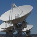
usually we (Peter, DG5ACX and me) do the antenna measurements outdoors with the arrangement shown in the picture. To measure the circular polarization, the antenna rotor is tilted by 90 degrees, so that the antenna to be examined can be rotated by 360 degrees about its own axis.
In the present case, however, this was not possible due to the rainy weather. We therefore carried out the measurements in our club room on a wooden table. Arrangement of objects 0.75 m above the table. Distance of the objects 1.30 m. The comparison with old outdoor measurements showed a good agreement. Since the rotor was not available, we rotated the log per transmission antenna by hand in steps of 45 degrees.
The connection of the measuring points by straight lines is certainly not professional. The scale in the diagram shows the values in dB.
73! Peter, DJ7GP
Hi Peter,
Pretty measurement setup. Can you kindly share with us radiation pattern measurement? (AZ & EL cuts) I would like to compare calculated and measured data.
Thanks,
73, Rasto
Hi Rasto,
yes of course I will provide you with the measurement results as soon as we have carried out the outdoor-measurements.
Of course you need the construction data of my duo band feed for the simulation. I would like to send them to you by email. My email address is: call (at) darc.de
73! Peter, DJ7GP
Hi folks,
I recently modified a few Airlink 60 antennas (see figure 1). This industrial 2.4GHz antenna is made by SSB Electronic. The original antenna has a vertically polarized patch in it, made by GlobeSat in Denmark. This patch is glued in the focal point to the inside of the radom (see figure 2).
I replaced this patch with a WA5VJB-patch, LHCP (Hi Z to compensate for the effect of the radom, as recommended by WA5VJB), so that the antenna is transmitting right hand circular polarization (RHCP) (see figure 3).
As I have a few of these antennas available, I could directly compare the circular antenna with the vertical linear one. The difference I measured in my QO-100 signal strength was between 2.1 to 2.5dB.
Best 73
Holger 'Geri', DK8KW
Figure 1: Airlink 60, an industrial prime focus dish made by SSB Electronic.
Figure 2: The inside of the antenna can be accessed from the back. Here, the original linear (vertical) polarized patch can be seen.
Figure 2: The original patch was replace with a WA5VJB patch.
 Display More
Peter,
Experimenting is always a good idea. A patch antenna with a single feed that is perfectly circular can't produce circular polarisation. There needs to be something else. I settled on the dual resonance method. The original POTY (it was not called that, that was Remco's idea) used an ellipse but that's hard to make, so I tried an approximation to an ellipse. A circular patch with notches, circular with tabs and the square with cut outs. The square was good enough and is easiest to make with simple tools, so that's what I ended up with. Other iterations had directors, choke rings and so on. Another way to do this dual resonance trick is with a feed and a tuning capacitor, but I found that really hard to get just right. G3RUH managed it but not with the waveguide. Achim did manage it but I don't know exactly how.
What wasn't obvious early on is were the simulations accurate? I was taking huge liberties with the meshing in the simulation and with the full version of CST we could probably design a more forgiving, broader band patch. In the end, its only when something is reproduced in hardware that you can be sure it works, or not. So, keep on cutting and trying because if it works in hardware, even without simulation, it works.
Mike
it was me who brough mike to the idea of the square with the cut corners (i have no lathe so peters feed was not easy to reproduce on the kitchen table) .. i calculated in sonnet lite and mike calculated in cst studio ... and end result was near identical
rest is history
difficult to build and tune ?? yes a bit ... but when exactly made shows a good circular pattern and is near spot on