

If it is possible then you can connect CTS to TX GND. But it is not absolutely necessary. The PTT signal from FT817 is also available via CAT command (you can enable this in the software). But via CAT the PTT detection is a little bit slower.
Posts by DL3DCW
-
-

I am sure it would work, but since my PC in the shack is already connected to the FT-817 and gqrx is perfectly working, I would like to avoid setting up a separate hardware only for SAT control.
The Python program you can download here: http://www.satcontrol.de/files/satcontrol.zip
Maybe that on your system some additional packages need to be installed. On the complete Raspberry image everything is already prepared.
-
Maybe this will work for you: SAT Controller SDR Nano
-
Ok thanks. I will try this.
-
My Pluto is connected via USB/LAN adapter to my network. With SDR console it works fine via network access.
But with the „software DVB-S demodulator“ i have no success. What settings are needed in this software to connect my Pluto via LAN?
-
Is it possible to connect a Pluto SDR via network? I tried it but without success.
-
Easy workaround: Use a 1GB, 2GB or 4GB Raspberry. You dont need 8GB for the image. On my 2GB Raspberry it works perfect.
-
Maybe the new 8GB Raspberry will be the problem. On my 2GB Pi it works well (think also on 1GB and 4GB).
-
PTT output modification Allnet ALL3075v3
This modification allows control main power (SUPPLY) and PTT (AMPLIFIER) independent with only one device
-
I use two Ubiqiti NanoStationM5 (5GHz) for the WLAN-Link (50m) to the Pluto. It works fine and stable without any problems (DATV).
To switch on/off complete Pluto equipment (power supply, PA etc.) i use Allnet ALL3075v3 which is connected to te second LAN port of the NanoStationM5. So you dont need a seperate network switch.
Additionally i have connected the yellow LED of the Allnet device via optocoupler to PTT input of the PA. So i can control power and PTT with only one device.
-
Next version will also support AMSAT-DL Up-Converter "UpCon6W"
-
Habe heute zwei Gelid-Wärmeleitpads eingebaut (3mm + 0,5mm): https://www.amazon.de/Unbekann…rmopad-dick/dp/B07CK31PST
Macht noch einmal ganz enorm etwas aus! Die Endstufen-Temperatur pendelt sich nun bei etwa 50°C ein (etwa 4W Dauerstrich)
Die Pads fühlen sich schon im rohen Zustand extrem kalt an. Sie sind allerdings recht spröde, so daß man etwas vorsichtig sein muss. Auch sind sie nicht sehr elastisch; sie federn daher kaum/schlecht zurück. Also möglichst nicht vor dem Einbau zusammendrücken.
Ich habe einen Sandwich aus 3mm + 0,5mm Pad montiert. Dieser lässt sich sehr gut auf 3mm komprimieren. Nach dem Zuschneiden kann man mit den Resten fast die ganze Platine abdecken. Die Bohrung in der Nähe der PA lässt sich nach dem Anbringen des Pads auf der Leiterkarte sehr gut mit einem kleinen Schraubenzieher freistechen.
Werde bei Gelegenheit noch mal testen wie groß die Drift des internen TCXO nun ist. Vielleicht ja nicht mehr ganz so extrem so das es notfalls auch ohne externe Referenz klappt.
-
Cable is 15m Aircell-7. Dish size is 85cm with Winkler 5-turn helix feed. Signal with this setup is 25dB over transponder noise.
-
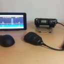
Complete station:
-
Die Sendefrequenz driftet dabei um etwa 750Hz (interner TCXO)
Die Drift habe ich mit einem kleinen externen TCXO vollständig eliminieren können (hinten rechts):
-
Danke für die Rückmeldung, Gerd. Dann scheint es wohl definitiv ein Problem mit dem zum Lieferumfang des UpCon6W gehörenden Wärmeleitpad zu geben. Ich habe auch noch mal die oben angegebenen Pads mit 12W/mK bestellt und werde berichten.
-

Pi3+B
Ohh, then you use the very old image "satcontrol_02.img.zip" ...

The actual image with a lot of improvements is "satcontrol_06.img.zip". It requires a Raspberry Pi 4B.
I recommend to use only the last actual image because the differences are too big. There are also significant changes in the user interface.
-
For the the menu you only have to press the "Set" button. Then all menu items will be show. This is new in the last versions so you don't need to click right mouse button)
A1: To adjust master signal press "Lock". Then GQRX automatically tunes to 10.706,000 MHz (-1,5 kHz).
A2: The engineering beacon is on 10.706,000 MHz (default setting, see screenshot in my last posting).
A3: After adjusting audio signal of the beacon to 1,5 kHz press "OK" (also see the same screenshot).Simple procedure:
1. Press "Set"
2. Press "Lock"
3. Adjust engineering beacon signal with mouse wheel to 1,5 kHz in audio spectrum
4. Press "OK"
5. Switch on "Drift correction"
Then in the ERR field you see the actual drift. After "Lock" procedure it starts at 0 Hz. Thats all.
NOTE: You need 2 SDR-Sticks. One for GQRX and one for the master signal (drift correction).
-
Hi Stefan,
thanks for response. Some things should be noted before operation:
1. Lock to master signal
First, the system must be set to a reference signal (menu item "Lock" ). This is used to calculate the actual LO frequency and as master signal for the software drift correction. Default setting is the engineering beacon of Es'hail-2 (menu item "Master"). With the preset RF frequency you have to adjust the peak in the audio spectrum to 1.5 kHz.
This process must be repeated occasionally if the LO frequency has drifted too far away. If you have problems, you should experiment with the parameters and possibly restart the program (unfortunately this function is not perfect at the moment).
2. Adjust beacon frequency
Fast fine adjustment is possible with a beacon signal in NB passband (button "Adjust"). Default setting is the middle beacon of QO-100 transponder (menu item "Beacon"). With the preset RF frequency you have to adjust the center of the signal in the audio spectrum to 1.5 kHz.
This procedure should be performed before each operation (after a short warm-up phase). Because the SDR software sometimes shows errors of some 100Hz. This often happens when you restart GQRX, change frequency ranges or if you tune via the big frequency indication digits. For tuning it will be better to use the mouse wheel and/or place mouse pointer to desired frequency in the waterfall. The fine adjustment should be checked regularly. In the future hopefully this step can be omitted.
At which step do you have problems?
Frank, DL3DCW
-
Habe heute testweise dieses Pad installiert: https://www.amazon.de/EC-360-Blue-4MM-Wärmeleitpad-50x50MM/dp/B0145SDN2O
Jetzt ist die Wärmeableitung deutlich zu spüren! Ein Riesenunterschied zum mitgelieferten Pad. Montageplatte und Kühlkörper werden jetzt endlich warm.
Im Dauerbetrieb mit 4W RF erreicht die Endstufe eine Temperatur von etwa 65°C (serielle Diagnosedaten). Ich finde das immer noch etwas viel; es lässt sich bestimmt noch weiter optimieren (besseres Pad >5W/mK verwenden).
Das 4mm Pad lässt sich auf etwa 3,5mm stauchen. Mehr sehr sollte es aber nicht sein da sich sonst die dünne Platine zu sehr verzieht. Eventuell könnte man ja ein 3mm Pad mit einer zusätzlichen dünnen Wärmeleitfolie verwenden.