Posts by SWL-Jonas

    I took my Multimeter today. And I once more confirmed that the biggest bug is sitting right in front of the computer.
    The reason why I go the strange osci reading was that the pin of the adapter I used to connect the WB+REF coax cable to the osci was broken. It took me quite a while to figure that out. I didn't expect to still get a partially correct reading when the hardware is broken like that. But in RF many things are possible I suppose :D
    Anyway another valuable experience. The readings my multimeter showed me were as you might expect. All the jumper pins gave the correct voltage all the coax sockets gave the voltage according to the jumper position. So I am back to the point that the LNB should work fine in theory but it doesn't.

    So I wanted to test both LNBs with the V3D again. But now I keep getting initClk on the display. It doesn't get past this state anymore. I cant remember seeing it before. I am not using any external reference only the built in clock. I have unplugged the power several times but it doesn't change anything.

    I just talked to Sigi, DG9BFC. He said, the newer Plutos with newer firmware can no longer be modified that easy.

    So depending on your firmware it is possible easily or with tricks only.

    I am very sure I did "hack" the Pluto to widen the bandwidth. But I also just tested with a local radio station (106.9 MHz) and it worked perfectly. So I think the range of the Pluto is not an issue.


    EDIT: You have a bias Tee, so: Pluto -> bias Tee-> NB of your lnb.

    V3D WB IN & 25MHz out -> WB out & 25MHz in of your lnb. Set Pluto to 740MHz. Should work.

    That was a great idea! I am learning a lot these days, thank you!

    I did just that. But the result was still an empty spectrum. So I replaced the modified the modified LNB with the unmodified one and ignored the second line. And i got the signals and beacons again.
    I tried to look around a bit to find possible error sources. And even though I have measured it before I measured the WB+Ref again. Surprisingly this is what I got:

    That seems like the LNB doesn't get voltage supply. The question is why?

    And how can I fix it? Another bias tee?

    Thank you for the instructions.
    I just tried to use the simplest possible set up for the Down Converter. Unmod. LNB -> Down Converter (no GPS, but either external clock reference of 10MHz from the osci or nothing at all) -> Pluto. I set the Jumper to 14V supply for the NB and 25 MHz, removed the connection between WB out and NB in and connected the LNB to the NB in as you suggested. I also configured the I/O device in Gqrx to 2 MHz bw.
    Then I swept through the spectrum in 100 KHz steps from 140 MHz to 150 MHz. But I coudn't see any of the beacons. somewhere around 146 MHz there was a very high peak. But It appeared out of the blue. It was suddelnly in the middle of the screen instead of shifting in with 100 KHz steps as i was sweeping. Do you ave any idea what might cause this or if its related to the problems I have?


    Alright, it seems you are not a ham-radio operator, otherwise you'd knew what a handheld or walkie talkie is.

    Yes, I am not ... yet. :D


    Ok, 40ish MHz an 25ish MHz is good! Means the TCXO in V3D is working and you have output, just not disciplined by GPS.

    Now, who modified the LNB? Was it someone who can check it ?

    Great that means there is hope.
    I have the modified LNB from the Shop here (https://shop.amsat-dl.org/produkt/qo-100-modifizierter-lnb/). So guess I could sent it back to be checked but I would like to be sure that it is really not working before I do so. And as things are going i Suspect there is something wrong with the V3D rather than the LNB. (I connected the bias tee to the Pluto and unmod. LNB again just to be sure the antenna and LNB are still correctly aligned and I was able nicely see the beacons and transmissions around 740 MHz)


    Do you have how i could further test whats wrong with the V3D?


    Cheers,

    Jonas

    Modified lnb: Is it known to work properly (like give it to someone to test in a different setup) , do you have access to a 24(25)MHz source?

    I cannot say if it is working properly. Unfortunately I also don't have anyone to give it to. But I have an oscilloscope at hand which can provide up to 25 MHz output.


    Do you have a frequency counter or shortwave receiver to verify 10MHz at the 10MHz output, 40MHz respectively and 24MHz at the WB-connector of V3D (careful, there is 18V , pull the jumper before that). Do not measure at the gps-module, measure at the dedicated outputs.

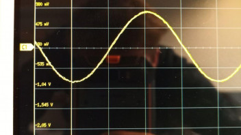
    I have measured those outputs today with the oscilloscope. I removed the GPS, out the jumper on PIn 3 and 4 and fed 10 MHz into Pin 5.

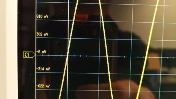
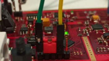
    (Green signal, yellow ground)

    Nevertheless tho whole time the display showed me the "Syslock : wait" screen. The dedicated outputs on the other hand were fine, except for some minor deviations. The 40 MHz was like 40.2 and the WB ref. was around 25. Though I had both jumpers (10A and 10B) removed and it should have been 24 I think.


    Then I tested the Down Converter set up with the unmodified LNB. As you showed in the picture I removed jumper 14A set 14B correctly, connected NB in to WB out and the WB in to the unmod. LNB. But still I wasn't able to get any proper reading. I think mainly because the Down Converter is still in the Syslock Wait state. For what ever reason.


    IIRC you can use V3D witht the gps removed , you then should also find those frequencies, just maybe a little offset. I'm still convinced that you loose the gps-satellites. BTW, it takes a couple of minutes for V3D to provide all outputs after it was powered up and has gps signals.

    You mean remove the GPS just like that and don't feed an external reference signal?

    Yes I have been waiting patiently for the out puts and the GPS.


    Can you transmit with a handheld on 437.075MHz in front of the lnb to see the 24th harmonic on 10490,400?

    Which LNB do you mean the modified?

    The only handheld i have Is my Phone (Ulefone armor 3WT) I don't really know if its sufficient. I guess I could also get my hands on a second Pluto SDR if that's better.


    How did you receive 739 MHz on gqrx? What was the setup? Was it different from the setup when you received on 144MHz? Just the lnb or did you exchange more components? Is there a short in the plastic bnc output->144MHz? When you use the unmodified lnb instead of the modified one, does the combo lnb -> V3D -> sdr(pluto?? or what?) ->gqrx work?

    I received the 739 MHz with the set up:
    unmod. LNB -> bias tee -> Pluto


    The 144 MHz is supposed to be the output frequency of the Down Converter in the set up:

    mod. LNB -> Down Converter -> Pluto


    For now i have only tested the unmod. LNB with the external reference from the osci which didn't work. I will test it with GPS and if possible without both. Do you have any Idea why I get syslock wait and I could fix it?


    Cheers
    Jonas

    Thanks for the plenty input!

    Did you reposition your GPS antenna? Where is your antenna located? Indoors? Can you try a different GPS antenna?

    Yes, I have re-positioned it. Originally it was inside directly behind the glass. I have put it outside and tilted it a bit. The signal seems to get more stable. But still not really reliable. Which is odd because I am at the top floor of the highest building in the area. I get between 4 and 7 satellites.
    Do you have any suggestions what GPS antenna would be a good choice?

    Please name the brand and model of your lnb.

    The unmodified LNB is a "LNB 1" digital single LNB by SCHWAIGER. Pretty standard with an LO of 9.75/10.6 GHz.


    How do you feed the reference from V3D to your modified lnb? The reference is on the wideband connector only, not on the NB-Connector. So if your lnb shares output and reference input on a single connector, you need to rethink the setup.

    I have two coax connections between mod. LNB and Down Converter. One for the NB and one for the WB+Reference.


    Had same effects with somtime GPS loss ... , mostly after new start of the converter.

    I changed the GPS Antenna, now without problem ...

    Maybe a try?


    73 de Robert

    Good Idea. May I ask which antenna you use?


    I promised you screenshots of the Gqrx:

    This is what I get with the bias tee and the unmodified LNB.


    This is the result when I use the modified LNB and the Down Converter. (Even when the display shows everything should be alright GPS wise.)


    I tried to measure the frequency on the GPS module but I wasn't getting anything that looked like a proper clock. I have to measure between GND (Pin 2) and Debug Output (Pin 4), right?

    I am not sure if I used the Oscilloscope correctly.


    I also made a very strange observation with the 40 MHz out put. When the display showed GPS running the frequency was not correct:


    But a few minutes later it was the other way round:


    Do you have any Idea what this could mean?

    Thank you very much for your patience!

    Jonas

    So if the display says "Syslock : wait" the GPS connection is lost?


    As for the dish I am very sure that the pointing is correct. I have a second unmodified LNB and a bias tee with which I am able to listen to the transmissions. I will get screenshots of the Gqrx when I'm back in the Lab.

    Also I was asking myself if I could test the GPS module and the Down Converter separately. You said if the GPS pins 3 and 4 are bridged the Down Converter uses a 10 MHz signal. In my version of the Down Converter this signal has to be provided by an external source, right?

    And for the GPS module: Could I power the module with 3.3 V and measure the frequency output at pin 4?

    Hi,

    Thanks for the quick reply!

    The GPS module seems fine, no shorting. I have checked the voltage its 3.3 V.
    I have experimented with the GPS antenna position. I am able to get enough satellites even though it takes some time, up to 5 min. But the display output is still making me wonder:

    First I get this: (don't get confused by the time on the display I took a loot of pictures the first ones didn't have sufficient quality)


    After quite a while it changes to:

    But as you can see in the background the PLL LED is still not on. Isn't it supposed to be on at this state?


    From then on it keeps changing back and forth to this:


    I have measured the external reference output and it provides a 40 MHz signal as it is to expect.

    However connecting the Pluto to the Down Converter output and reading the data with Gqrx I can't even see the beacons around 144.5 MHz.
    When I only connect the reference input to the Pluto and an antenna to the Rx I am able to get proper reading of the local radio stations.


    I am not sure what goes wrong here.

    I am a little confused now.

    Do you mean the pins 3 and 4 of the display connection providing the SCL (sometimes referred as SDK, Clock)?
    Or are you referring to other pins on the Down Converter? The only pins with jumpers on the Down Converter I know are the ones to define polarization and LO frequency of the LNB.


    ****EDIT*****

    I think i know whats going on!! Your display shows V3D is set to external 10MHz Reference Input! Remove Jumper on Pin 3 and 4. OTOH, how can you install a gps-rx AND the jumper? hm...


    ****EDIT*****

    Sorry, I understand now.

    I found what you mean:
    https://amsat-dl.org/en/der-neue-amsat-dl-qo-100-downconverter-v3d/ Figure 8, right?
    Those are the pins that the GPS module is plugged onto. Pins 3 and 4 are for the serial connection of the GPS and the debug output.
    The GPS module is occupying both pins so I assume there should be everything in order. But as you mentioned the display suggests that the Down Converter is expecting a 10 MHz external reference input. How can this happen?
    And more important how can it be fixed?

    Thank you for the Schematic it was very helpful.
    it seems the display works fine but I am not getting the detailed information about the GPS (like here in image 9, https://amsat-dl.org/der-neue-…qo-100-downconverter-v3d/). Instead I get a different screen.

    I tried the display without connection the DownConverter to the LNB beacuse its not at hand at the moment. Is that the reason for the different screen or can I manually switch the displayed information?

    Cheers
    Jonas

    Hi,


    I am relatively new to RF technology.

    For starters I have set up a small ground station to receive QO100. But now I experience very similar problems.
    In the beginning the DownConverter V3d (with GPS receiver) worked just fine. I am using a PlutoSDR and the modified LNB as well.
    For better signal stability I wanted to feed the 40 MHz clock reference from the DownConverter to the Pluto. So I modified the Pluto in order to connect the clock.
    Unfortunately the readings I am getting now are not what I expected at all. So I checked the Pluto without DownConverter. I connected the signal generator of an Osci to the clock input of the Pluto. Receiving the local radio stations with this set up worked nicely. To verify that the rest of the setup works correctly I built a simple Bias Tee. With the Bias Tee (antenna, Bias Tee, Pluto) I can receive the signals again.
    The DownConverter however is not working as it should. I have observed the following:


    1) GPS receiver LEDs:
    PLL: off
    Power: blinking
    GPS sat connection: on


    Though I have to say that I think i saw the PLL LED on for a second just after switching on the power for the DownConverter. But that was not reproducible a second time. I tried several times.

    2) DownConverter LEDs:
    Power supply(A): on
    Down mixer lock(B): off

    (C) : mostly off but blinks once in a while shortly
    Central PLL sync. (D): blinks


    3) I also measured several outputs of the DownConverter. Some measurements differed from the normal values.


    The 40 MHz clock output was giving 35.08 MHz or 48 MHz (varying from test to test).
    The frequency of the wide band output is 28 MHz instead of 25 MHz.

    The frequency at the GPS receiver 8.77 MHz instead of the expected 10 MHz.

    The Jumpers for LNB reference selection are at 25 MHz selection. (10 A bridged)


    Does anybody know the diagnosis for these symptoms?
    I am grateful for every hint to locate the error or further tests I could run.

    Thank you very much.
    Cheers,
    Jonas