Posts by AB6RF

    That is a good suggestion, I will try to get some small copper tube.

    And yes, I have been thinking about the orientation of the Plexiglas support.

    From a mechanical perspective, it would be best to have the support in vertical orientation, but that puts the support in same orientation with the V polarization of the NB transponder.

    That sounds like it could be a problem.

    ... You don't need to wait for your trip to the EU, you can see and measure the attenuation on 3cm by the helix on every TV satellite. .... and optimize if necessary.


    73

    Thank you for the comment.


    Yes, that's true, I might do that testing here.


    What is causing me some confusion is the material choice for the helix support.

    Some sources say that Acrylic has very low loss tangent, but other sources do not agree.

    I might make another support using Polypropylene.


    One observation about the helix.

    If I don't have a support structure on "both sides" of the helix, the copper wire wants to spring back to a larger diameter.

    Only way to keep the helix at 42mm diameter is to use this kind of support that holds the wire on both sides of the turns.

    Today I worked on the antenna feed(s).


    I'm going to make two feeds, and when I come to Europe, I'll test which one works better and use that.

    I'll make a normal dual-band POTY, and a helix + LNB.

    Today I started to work on the helix.


    I used 2mm diameter (US 12 AWG) wire for the helix, little bit thinner than some have used, but I'm trying to minimize the shadowing on the 10GHz feed.

    But with that thin wire the helix is pretty wobbly if not supported well.

    So I made a support using Acrylic, or Plexiglas or what ever you want to call it.


    As far as I know, the Acrylic has a low dielectric constant and very low loss tangent.


    Here's a picture of just the parts coming together.

    I will have to fit the LNB (with feed horn) into the helix reflector before I permanently mount and tune the helix.


    Some progress.


    I got two LNBs to modify for an external 25 MHz Reference.


    One of the LNAs uses 1x RT320M, and the other one uses 2x NXP TFF1014.


    Looking at the internal oscillator signals on an oscilloscope, it's clear that what's been said on this board already many times is correct.

    The RTM320M uses a normal CMOS inverter oscillator, and the crystal can be replaced by feeding the external Ref signal into the Xtal input pin.


    But the TFF1014 is different, and I follow the guidance to feed both Xtal pins with balanced signal.

    (as recommended in the NXP app note)

    https://www.nxp.com/docs/en/application-note/AN11516.pdf

    I'll use a small balun to make the balanced signal from the 50ohm external Ref.


    AB6RF

    It was the Thanksgiving holiday here in the US, so I had time again to work on this stuff.

    Today I tested my “EBay amplifier”.


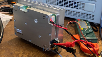
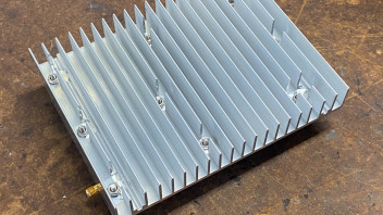
    Very low cost, and has a nice and solid machined aluminum housing, but no heatsink.

    So my first step was to find suitable heatsink stock and drill the mounting holes.

    I don’t have metal machining tools, just hand saws and drills etc. so the heatsink machining is not pretty but it works.


    The amp works fine, and puts out good power.

    With 26 volt VDD, I measured 30 W out at -8dBm in.


    The amplifier is not tuned for 2.4 GHz. It’s best at 2.25 GHz, where it has 3.5dB more gain.

    But it’s fine, this is already more than I’ll need, so I'm not going mess the with the matching.

    (The amp also has an internal isolator that is not designed for 2.4 GHz, it would be easy to remove the isolator and get more gain, but there’s no need)

    Hi everyone,


    I've started to put together a station for the QO-100, and since I don't have a personal blog, or a personal web page, I'll try to document my progress here. Hopefully it's OK with everyone.


    The setup will be based on an Adalm Pluto.

    I have couple useful LNB's at hand, that I will modify for an external 25MHz reference.


    First step, I made a board that serves three functions.

    1) Bias-T injection for the LNB DC

    2) 740 MHz RX filter

    3) Source for the 25MHz LNB reference


    Just as a personal preference, I didn't choose to use GPS locked PLL. Instead, I decided to use a OCXO for the LNB 25 MHz, and another OCXO for the Pluto.


    Picture of my bias-T/OCXO/filter board.


    Frequency response of the 25 MHz LPF, and the resulting waveform.
    (notice that in the oscilloscope FFT, the y-axis is 20dB per division, so most harmonics are about -70dBc)


    Mikko, AB6RF