Posts by PA5Y


    Having thought about this the RF detector was working perfectly well. A 2 tone signal looks like 100% AM so of course the detector switches off at the zero crossings, this would never happen with an SSB/CW or FT8 signal. Only a 2 tone test would cause this behaviour.


    I feel foolish :)


    73


    Conrad PA5Y

    Hello Thomas, I go on vacation next week but hope to have full duplex ready upon my return. Currently I only have RX on the dish but I have a POTY ready to go, I am looking forward to our first QSO. I have a 1,1m Triax dish.


    I hope that my experience with this amplifier is useful to others.


    73


    Conrad PA5Y

    Hello Thomas.


    Of course I have read that thread. My amplifier has 16dB gain as I have indicated in my posts above. One obvious difference is that the attenuator is not populated on my amplifier. Instead there is a 0 ohm resistor for the series element and the shunt elements are not populated. It was delivered in an EDUP box and it appears to be genuine but who knows.


    Or are you suggesting that I do not know how to measure the gain of an amplifier :)


    73


    Conrad PA5Y

    Hello Thomas, yes of course it is. That does not mean that you cannot use an external 12V supply. I don't like these 12V AC/DC plug in SMPSUs they radiate noise on the lower bands. I operate on 144MHz EME and such 'wall warts' are noisy and I never use them in my shack. I have 12V linear supplies in the shack instead.


    The internal regulator reduces the 12V DC down to 6V for the PA, there is also another regulator to reduce the 6V in order to generate the necessary bias supplies for the YP-242034 PA ICs.


    If you are relying on RF sensing for RX/TX switching then you might want to check that you don't have these sidebands.


    It could also be that my unit was defective, the easiest solution was to short pins 4 and 5 on the IC TPH2504 and hence disable RX/TX switching. Now the performance of this amplifier is quite reasonable, especially considering the price.


    Regards


    Conrad PA5Y

    I found the problem. I looked at the main DC and bias supplies and I noticed that there were square wave pulses at the same frequency as the tone separation.

    1. I disconnected the main supply and fed 6V externally via the 2 BLMs, the problem was still there.
    2. I realized that RX/TX changeover was occurring at the same frequency as the tone separation
    3. As soon as I shorted pins 4 and 5 on the IC TPH2504 the problem went away

    It was interesting that this behavior occurred at all drive levels so I suspect that there was a problem with the input power detector, I did not investigate further as I always intended to run the amplifier in TX mode. In order to keep things thermally stable I will use a FET switch to turn on the 6V supply when it TX. Next I will try with the internal SMPSU again, it is probably fine.


    On my unit the input attenuator is not populated and the gain is 16dB. 1dB compression occurs at 4W PEP. The IMD5 does not always reduce at reduced drive but the general trend is OK. This PA is fine for use on the transponder at 4W PEP, or 1W per tone for 2 tone testing.


    Tone spacing 1.2kHz, 6V DC fed from bench PSU


    Drive per tone (dBm)PEPIMD3 ref toneIMD5 ref toneIMD7 ref tone
    8.21W-36.0-39.0-46.0
    11.22W-37.3-40.3-43.0
    12.83w-35.8-45.8-42
    15.54W-35.0-40.0-41.5

    I have just checked the gain again and I do see 16dB , this is much more than others have reported. The PCB is marked 2201 for what it is worth.


    73 Conrad PA5Y

    Thanks Sandro.


    I had a look under a microscope and one device has YP242034 printed on it and the other YP242084, as the ....84 does not exist it seems that this is a printing defect. I am going to connect an external 6V supply next. I checked for dry joints etc and there was nothing. It appears that I have a 15kHz oscillation somewhere.


    There are many of these amplifiers in use so I am surprised that nobody has measured the 2 tone IMD before. I hope that I have an isolated case.


    73


    Conrad PA5Y

    Hello Thomas, each measurement was done for a few seconds only, the problem that I see is not thermal. If I can cure the instability then I will add a heat sink and a blower as it is good engineering.


    As I said these spurs are 40dB down on the main signal and so would most likely be inaudible on the transponder. It could be something simple like a dry joint on a s capacitor on my example. I would very much like it if someone else could check another amplifier on a spectrum analyzer.


    Best Regards


    Conrad PA5Y

    Hi all, I finally got the EP-EB003, it would appear that the main regulator is not OK. First the 2 tone drive signal from an IFR2026 signal generator and an F1OPA driver amplifier, 14dBm per tone. Nice and clean. Sorry for the photos, in future I will grab the trace from the spectrum analyzer.


    Now 4W PEP from the EP-EB003, 30dBm (1W) per tone


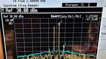
    -35dBc 3rd order referenced to the tone, 20kHz span, not as good as I would like put probably just about acceptable. But look how the IMD comes back up. That is not right of course. So now look at 100kHz span, very ugly and it looks as though the regulator is oscillating.


    Yuk!

    These sidebands are around -40dBc so they would in the noise for most people but I would never radiate such a signal. Reducing the drive level does not improve the situation.


    Does anybody know what the voltage regulator device is in these amplifiers? I would have had a poke around but could not find a suitable Allen key to take the lid off. Of course I have one.... somewhere.


    The power supply used for testing was a big linear supply and as you can see from the first photo the drive was clean. This comes from the PA.


    Has anyone else got an EP-AB003 that they can check? You really should!


    73


    Conrad PA5Y

    Has anybody checked the IMD performance of the EP-EB003? I may use one as a driver for a DG0VE PA, I need a little under 30dBm. I expect that it is quite reasonable at this level.


    73 Conrad PA5Y

    Hello all. I am just about to order a roof mount (tagelvoet) that uses 60 x 40 x 5mm concrete tiles for ballast. The ballast weight is approximately 108kg


    My intention is to mount the dish and mount on top of a flat metal shipping container that I use for storage. It is clear in the direction of the satellite. I have a Triax TDS 110 offset fed dish. The standard pole for this roof mount is 70cm long which means that the lower edge of the dish will be around 25 cm above the metal roof and around 1.5m from a wall to the West of the dish.


    How much clearance do I need?


    I can buy a 120cm pole but then I should probably go to a 60mm diameter pole instead of the supplied 48mm.


    I have no idea what is needed, I don't want to pick up noise from the container.


    Thanks in advance.


    Conrad PA5Y

    Hello Peter, shielding and weatherproofing is my main concern. I see lots of foil and braid shielded cables but the braid always seems poor. Of course unlike my other systems the sat system will be fixed so I do not have to worry so much about foil cracking. This is a big issue for my other systems with rotators.


    I expect that I will have to add some additional attenuation!


    73 Conrad PA5Y

    Hello Thomas


    Sorry for the late reply, I was not home until late.


    I read that the POTY is around 2.5dB better on TX. Most attribute this to the fact that the POTY has better circularity. I decided the best way to tell would be to confirm it for myself.


    Regards


    Conrad PA5Y

    Thanks for explaining that Martin, very helpful.


    I have options for receiving. I can use an Afedri SDR-VHF so can directly receive wherever the IF appears, I have to lock the Afedri to 80MHz but I have done this with a Perseus RX so I do not expect problems . However most likely I will use my ANAN-100D in duplex mode. This means I will need to convert from the IF to 28MHz.


    On TX I have made a 144>2400 upconverter from parts I already had, it works beautifully at up to 18W PEP with 3rd orders at -42dBc. PN is much better than needed. Also in the path is HA1YA 144/28 XVTR, a 116 MHz Kune XO locked to 10MHz, For TX I have a 7dBm mixer, 2256MHz LO, SAW filter, UTMS PA and one of those nice Band pass filters from Poland. LO leakage is -78dBc, IF leakage better than I can easily measure (>100dBc). I expect to use a lot less power than 18W with a Triax 1.1m dish. Of course it still needs boxing up. I will need 6m of coax. Hopefully I will be QRV in a 2-3 weeks.


    Regards


    Conrad PA5Y

    Hello all, in my haste I bought a BAMAtech dual band feed with an LNA included. I realise now that I should have bought a POTY. Does anyone have any experience of removing the LNB from a BAMAtech DJ7GP dual band feed? Is it easy? I do not have the feed yet it is in the post. In anticipation I got a 24MHz PLL from Dieter DF9NP and so I am tied to using an LNB that requires a 24MHz reference. It would be easiest to remove the LNB from the BAMAtech feed. I assume that the waveguide is merely pushed into the LNB and then some silicone sealant is applied.


    I am annoyed with myself for not realising that the BAMAtech feed is not a POTY.


    Regards


    Conrad PA5Y