Posts by dl2kp
-
-
Hi,
as I don´t trust in the plastic Adalm-Pluto enclusure for mikrowave applications, the hardware was installed into a Hammond 1590 BB box. This is even cheaper than milling a home made aluminium case, because of the actual super high alu prices.
Now I am not shure to install the newest firmware V.0.35 because I would like to install the french software for MiniTiouner, too. Which version of firmware is recommended? Who has experience with this softwareß
Vy 73,
George,
dl2kp
-
Hallo Matthias,
vielen Dank für die schnelle Antwort. Was heißt neuer Pluto? Ich habe hier zwei Plutos mit Version C, die allerdings auf der Platine die Version D verzeichnet hat. Wie kann man das feststellen, was neu ist?
Gruß
Georg
-
Hallo Mathias,
zu Deinem Konzept habe ich eine grundsätzliche Frage: Wozu benötigt man ein USB OTG? Was für eine Funktion hat er?
Der Adalm-Pluto hat einen eigenen Eingang für die 5-Volt Versorgung und den USB-Ethernet Adapter läßt sich direkt in den USB-Anschluß stecken. Habe ich da irgend eine Funktion übersehen?
Gruß
Georg
dl2kp
-
Hi,
I am trying to register myself into VivaDatTV forum to download MiniTiouner software but didn´t get an activating account mail, since days. Unfortunately I cannot see any possibility to contact the board admistrator. Could anybody give me an advise how to proceed?
Vy73,
George
dl2kp
-
Actually, I don´t see a major problem. What you need is to build up a chemical bridge between the raw material and the glue. This could be done through a so called primer linke LOCTITE 770. Subsequent teflon can be glued with epoxy resin like LOCTITE 406. The only disadvantage is the high price.
Vy73,
Georg
dl2kp
-
Hi Matthias,
you can see it here in the forum under antenna :
"Mate LNB and Patchantenna".
The LNB-clamp has a diameter of 50mm. Therefore a 50mm waste pipe slides over it easily. On the other side the pipe is glued to the POM-cover of the bigger part.
At the end the patch will be covered by a 0.5mm teflon sheet glued to a removable ring.
73,
George
-
-
-
Hi Sigi,
the Poty is a coupled system consisting out of two antennas with a phase-shift of 90deg. Where at resonance you get a perfect circular polarisation. This point is exactly at the top of the impedance loop. Resonance means that the imaginary part of the komplex impedance is zero. Therefore the location of the loop-top shall be in the middle of the smith chart at the operation frequency. As soon as the top moves out of the middle, you get two resonances and the polarisation starts to be elliptical. In the extreme it will end to be linear.
I think, we got it!
P.S.: To clarify the 45deg angle you should know that the impedance of the shorter antenna shall be Z=50 -j50Ohm and the other Z=50+j50Ohm. Both impedances summarizes to real 50Ohm. The operational frequence at 50Ohm is in the middle of the frequencies of the two antennas. This means that one antenna is operated below the operation frequence and the other above. According to your description above.
-
Hi Benno,
did you test the circularity? The SWR is useless to judge the circularity.
George
DL2KP
-
Hi Benno,
Concerning the white lense, you are right. I am in the process to build two systems. One for a prime focus dish and another for an offset dish.
George, DL2KP
-
Hi Mikko,
why you don`t tune S11 to one peek, only? Here in the forum are different opinions. Is it possible that the circularity will be lost?
Could you be so kind to measure your poty tuned to one dip, only? This could explain the words by Mike Willis,G0MJW, that one dip will not produce a good circularity. I don´t belief it.
Which dish are you going to use?
DL2KP.
-
Hi Hebert,
leider nein. Dort wird eine Helix mit 3 Windungen und einem -10dB Öffungungswinkel von 105 Grad gearbeitet. Angegeben wird auch für ein f/D=0,66 ein Winkel von ca.70Grad. Das stimmt mit meinen Infos überein. Leider hat mein offset Spiegel ein f/D von 0,36.
DL6YCL has an offset-dish with f/D=0,66 and an illumination angle of 105deg. He mentioned that a Poty has an angle of 110deg.
73
George
-
Hello,
the calculation (HDL_ANT2_WinForms by W1GHZ) for my offset dish pruduced following results:
- f/D = 0,36, illumination small axis = 68,1deg and a recommendation for -3dB beamwidth = 38,8deg.
With that in mind various helices were calculated. The best result was with 9turns:
So far,this result does not match the recommendation. Compared with all the publications in the net and here in the forum the amout of turns is more or less doubled. I also couldn`t find any discussion about matching the helix and dish illumination. It is clear that this should match, but nobody does take care of this subject.
Further more, I think that a patch antenna will not be acceptable for this f/D because of the broad overspill.
My concern is, that such a helix will creat troubles with my neighbors wlan.
What are your experience and recommendations
-
Hi,
after reading through "SWR POTY verbessern" and the comment by DG9FC I tuned my Poty bending all 4 corners carefully. Now I got this result:
Both resonancies vanished and one resonance dip with about -55dB remained. I am very curious about the S11 amount. Maybe my LibreVNA is the reason or/and the measurement surrounding in my shack. I have to remeasure it when mounted to the dish. An amount between -25 and -30dB would be reasonable.
Vy 73,
George
DL2KP
-
Hi,
I couldn´t suffer that an 1.2m dish was unused in my garden.
Therefore, I decided to construct my own QO-100 ground station. Here the feed was analysed with sonnet:
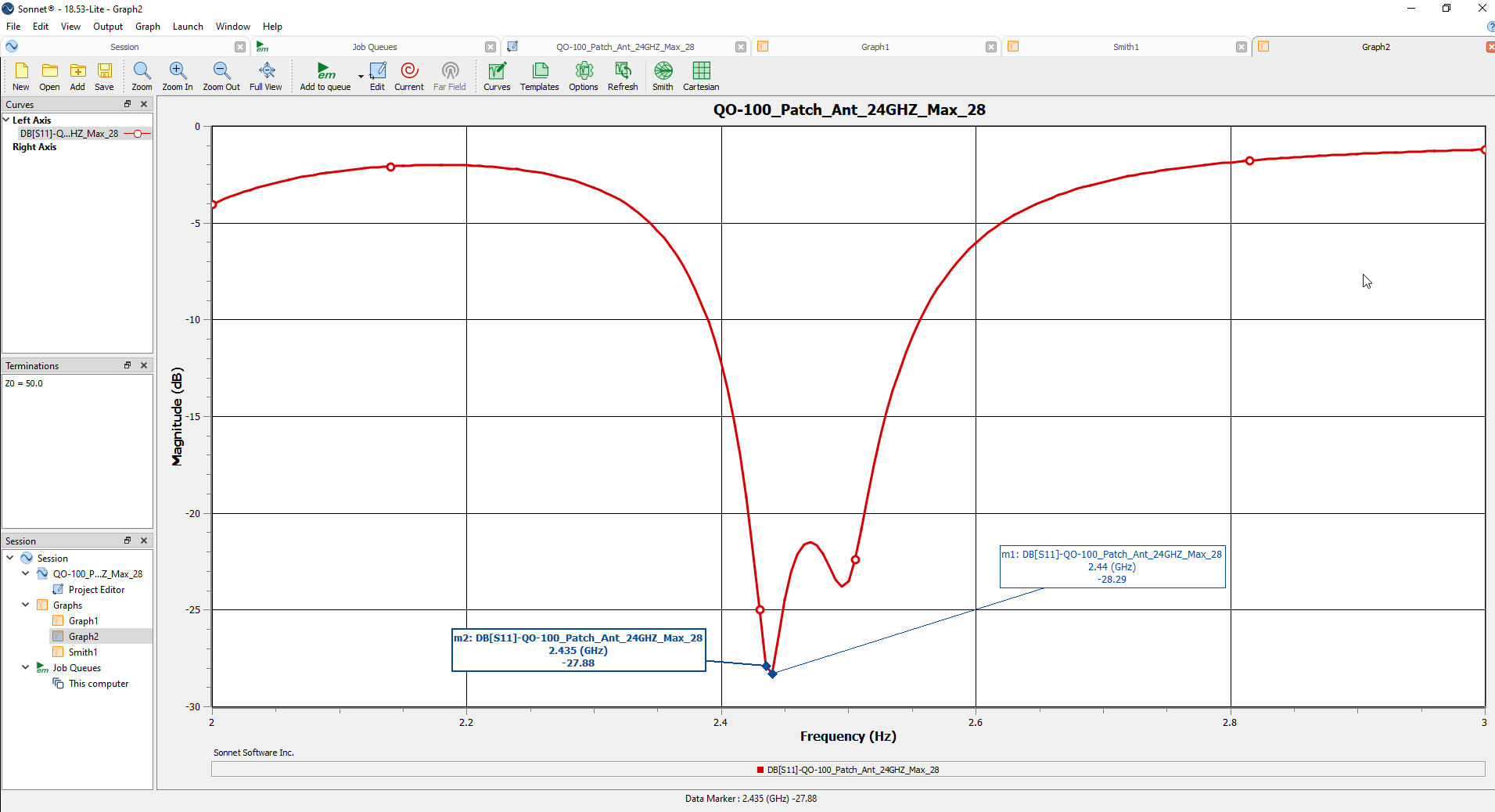
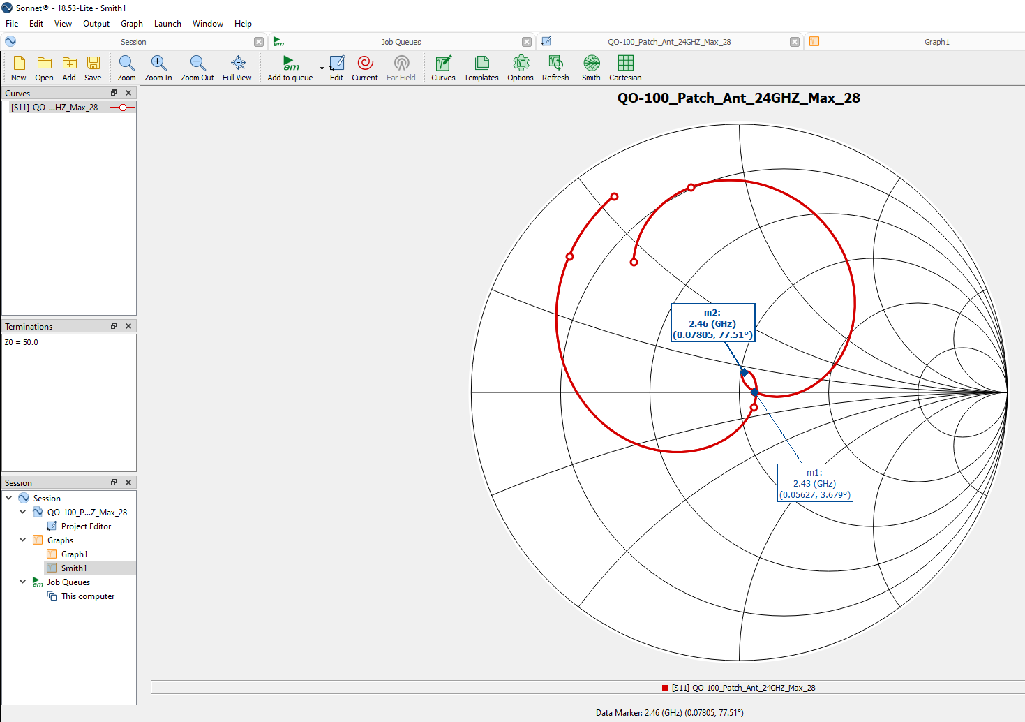
Unfortunately, I was not able to shift the frequency down to 2.4GHz. Sonnet light allows to analyse the antenna, only. Optimization is obviously in the full version possible, only.
Nevertheless, I started to construct the feed, looking forward what will happen.
After everything was soldered the first measurement was taken:
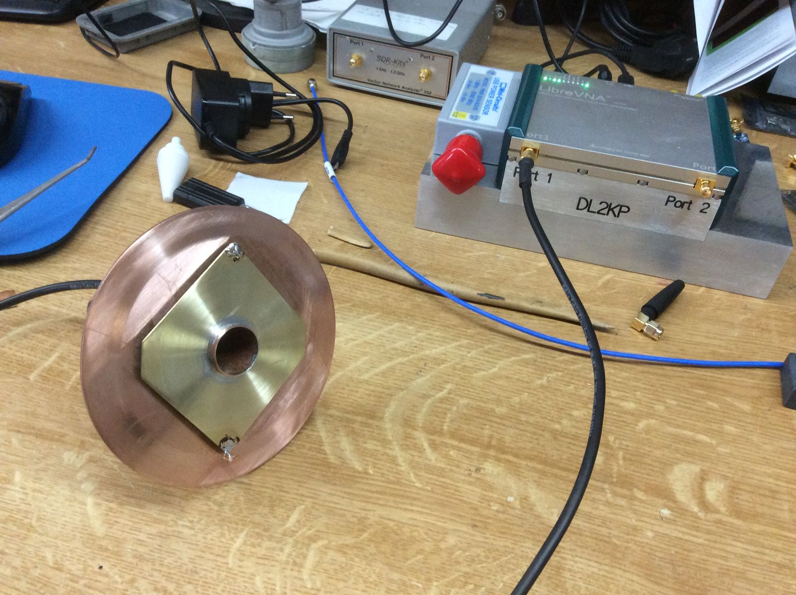
The first measurement after construction:
I have no experience to interprete this S11 trace. My guess ist, that the circular polarisation is not very impressive. So I played around and soldered some copper to the longer edge. At the end everything was removed. Solder remained at the two edges with following result:
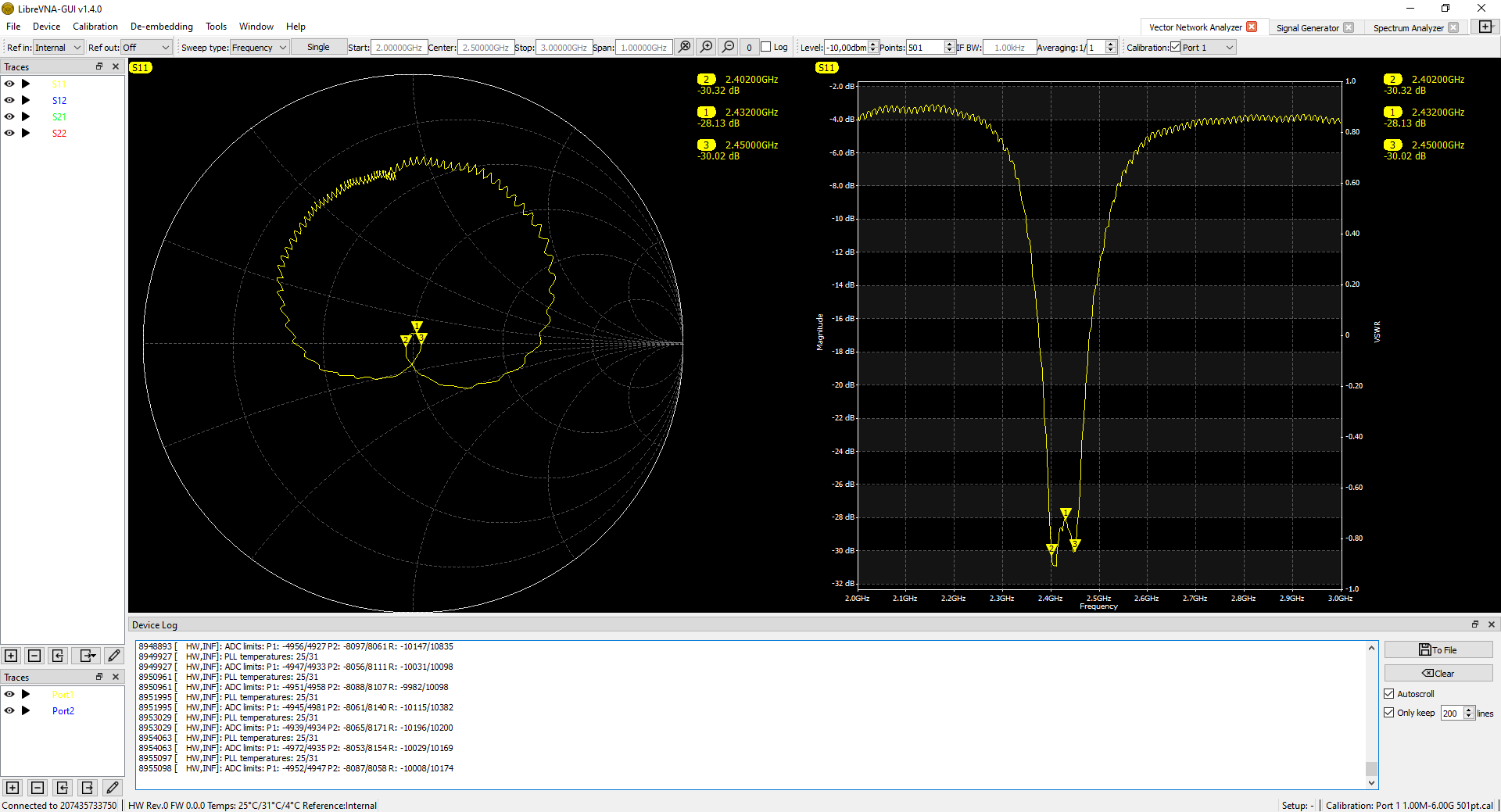
I have no clue why the solder will change the trace. I have to admit that all the measurements were done in my shack. Maybe this is the result off all the reflections.
Vy 73,
George,
dl2kp
P.S.: In the meantime I know the reason. The solder changes the thickness of the patch and so far the er of the poty-antenna. Changing er results in a significant detuning.
-
How can I find your post #36? I don´t see a possibility to search for post #36. What is the title?
-
Hi,
now I found the necessary information here in the forum. See posting: "Cmoputer Analysis of dual band dish feed (G0MJW,.....).
-
Hi,
to calculate the illumination of my dish, I need the radiation field of the patch antenna. According to the discription by G0MJW in Dubus2/2019 the dish was recalculated with sonnet light software. Unfortunately, sonnet does not show neither the -10dB-illumination angle of the feed nor the radiation pattern. There are lot of publications on the patch antenna, but nothing about the radiation. Does anybody know how to calculate the illumination angle of a patch feed with a free available software?
Vy 73,
George
DL2KP