

Normally i don't want to discuss this topic. I expected it somehow we will come to the situation as we have now with uncoordinated uplinks. The commercial satellite operators use upc uplink power control to avoid this kind of problems. We got a present to use this really expensive geostationery transparent transponder and have to know the following: Normally there is at the output of the TWT a circulator and load mounted. If you (users) transmit with to much rf power, bad spectrum or out of the frequency range defined by the bandplan rf will be reflected at the small filters (omuxe) and a temperatur raise at the load mounted at the circulator will trigger a warnung and later a alarm. This makes people in the controlroom nervous. There are alot of other effects. The aim is to make you aware its not like shortwave where you can't damage the troposhaere. To learn from this situation for future satellites (if we ever have this chance again in our live) there must be a kind of OBP (onboard processor) implemented. The sw can do a FFT and notch out unwanted signals. Stations with high power won't be downlinked. In germany there are some developments on that. (e. g. google for Heinrich Hertz satellite). But to fly this on a commercial satellite for HamRadio use you need flight heritage and its extremly expensive and normally not reachable for amateurs. Much easier and cheaper is to follow the rules given by AMSAT. Thanks friends!
Posts by DH0SK
-
-
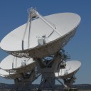
Maybe this is now a kind of dish sailing boot.

-
 Display More
Hallo SWL-Oliver,
Ich verstehe Deine Frage nicht so ganz.
Was hat FT-817 oder TS 790 mit dem Ganzen zu tun?
RX wird doch über 2 RTL-Sticks gelöst.
73 de DH2VH, Volker
The cat Interface is also supported from the sw
-
The WG of the Poty needs to be at the same place as the feed of the LNB was before. Exactly the same plane. At 10GHz its extrem sensitiv. 1cm mechanical mismatch is paid by loss of 3dB.
It takes me a while with my 60cm prime focus. Now it works wonderful at fully waterresistant in an grey water tube which you can buy at the local stores (Baunarkt) . See picture below if my minimal compact system for portable activity.
-
 Display More
@all participants of out great event:
We were nearly up to seventy people that evening and had nearly up to five hours for having dinner together and very good discussions going on at the tables. All enjoyed this evening and the whole group decided to do this again the saturday evening next year on the HamRadio show at the same place.
I ask all of you making photos during this evening to post them here.
Many thanks to all participants.. without you this evening won´t be that event we had together.
Have a save trip from the fair home.. I am glad you were there.. and hoping seeing you ther again next year..

Hello Heiner, wonderful but my collegues wants to drive back to the camping place at Tettnang. But i met alot of OMs after the presentation. Thanks for organization. Maybe next year. Attached pictures from my portable station at the camping ground
-
Now the POTY is water resistent
I changed to a Prime-Focus Reflector.
I assume for the Prime-Focus f/D : 0.4 the WG needs no lens - is that correct?
-
do1ctl Frank in the middle I have a hole for the 22mm wavegide an the I put the Venton lens on it. works in this way also with 10Ghz because the 10 GHz is not going though the endcap..
Normally 10GHz should work. I used this grey water tubes since long time ago for our 10GHz ATV repeaters slot antennas as random. Never seen anay degradation. They are also UV resistent. After 15 years outside i dismounted the slot antenne from the water tube random an they looked as new. The grey tubes are perfekt..
-
As promised here a short feedback to the Poty antenna i soldered at the wrong side. I resoldered the patch and after a smal tune (by optimizing the patch reflector distance) the measurement was fine - 20dB S11. First test gave me better results as before with the helical antenna. I need to reduce the output power now
For me its one of the best solution - electrical and mechanical.
The spurs were still there - it tuned an old interdigital filter (see picture) and the problem with spurs/harmonics were solved.
Thanks for that nice antenne - next challenge to make it water and winter restistance.
73 Kai DH0SK
-
It is only possible to get interference if there is a strong harmonic content - 2.4 GHz signal will not propagate down the waveguide. The 3mm spacing is critical, going to 1.5mm does not work so something is wrong with the patch. You should see 16-17 dB return loss.
Edit - I just looked at the photo. The patch is built incorrectly. The feed is in the wrong place.
Yes, this is what i expected from the WG. I havn't had the blocking problem with the Helical antenna used before.
Maybe the hormonic rejection is better with the Helical antenna.
At the weekend I will change the Patch and add a S-band bandpath to avoid harmonics. Maybe the problem is solved with that effect.
I will report.
Kai
-

Solving the problem with duplex, I don't think so. Others use this antenna e.g. with ATV on the WB tpx in duplex mode with success.
Anyway, I am curious what your perceived performance is when the 'Erreger' makes LHCP (into a dish).
Simulations and practice show that the antenna makes CP with a good axial ratio,
I will let you know at the weekend - if it has a good crosspol xpd i would assume i will be to strong...😉
But when i understood correct it depends a little bit of the tuning of both resonances to get the correct phase shifting? Maybe i was more linear than CP. I expect at least 10-12dB practical xpd for that antenna design and focal lenghts.
Lets use this mistake as a good practical justification for your simulation.
73 de Kai
-
Yes, that impacts LHCP pol, so mounted in front of a dish it has to be LHCP, so the dish reflects RHCP. See also HB9PZK's independent analysis of the POTY.
Yes i know
your right i did it in a hurry on the weekend without looking to the PDF. But i wondering my signalstrenght was the same as the left hand Helix. I expected a much lower signal. Its a nice experiment to check the polarisation. I will change at the weekend.Maybe this will solve the problem with the blocking of the RX while transmitting..
73 de DH0SK
-
Hello all POTY users,
i just ready built my POTY and take yesterday some measurements. It was not so easy to come to a <-20dB matching in S-band. With new soldering and changing the distance from 3mm to 1,5mm i got ~ -17dB max.
First transmit test gave same results as before with my Helix solution mounted above the Pollin LNB (out of focus). The receive part with Pollin LNB gave exact the same signal level as the standard feedhorn mounted before.
The biggest disadvantage is the fact that the uplink signal totally interfeering with the X-band downlink. The isolation between up- and downlink seems really bad in my case.
But i know that alot of station do not have this kind of problem - maybe it's the Pollin LNB or someone have an idea why it is so extremly in compare to my Helix setup.
Duplex is not possible anymore so i have to go back to the Helix solution which gave me less mechanical stability for portable use.
I am intersting if someone can report the same behaviour or better have an idea how to solve this issue? Is someone doing the test POTY-POLLIN LNB ?
Best Regards
Kai DH0SK
*** Aahh shit - just saw that i solder the patch on the wrong side
 hmm is this impacting the LHCP polarization ?
 -
 Display More
Hallo Armin.
Ich danke Dir für das Projekt. Da ich keine externen Taktgeber habe, werde ich wohl auf eine interne TCXO-Lösung setzen (müssen).
73
Marco
Pollin Elektronik GM201 Golden Media 2,45€. I can use it without drift compensation with RTL dongle and Raspi.
-
 Display More
I'm using this dish with Patch antenna from G3RUH and am very happy with..
James has some in stock still..
73 Guntram oe9dgv.
Seen the post from Peter i searched
in the cellar and found this - maybe its a good idea to change one of them to the Helix feed shown by Peter. I collect alot of things during the years - both are 60cm in diameter but not so precise i would say.
Lets try - i will report.
-
The software is only available as complete image for raspberry pi.
Hello Frank, the receive system is now running together with my TX part. Its now a standalone solution for up-downlink. Thanks for the image incl. drift control. Would be fine to see some new image from your side in the future with some improvements - many thanks!
Kai
-
Start Gqrx alone (without SAT Controller software) and test both SDR-Sticks (rtl=0 and rtl=1).
Current version is satcontrol_01.img.zip.
Although I had planned a newer version (and also hardware), the demand seems to be very low. In addition, I have received almost no feedback on the existing version.
Because my own raspberry setup is running very well I think I will spend my time to other projects
Hello Frank,
thanks for the quick feedback. Now both RTL sticks are working fine. The usb cable to one of them was not ok. Maybe broken china quality.
The drift compensation is not working properly at the moment. The frequency is jumping all the time more than 25kHz but i am sure i made something wrong in the calibration process and spent not to much time on that at the moment.
Please move on with that project i am sure alot of amateurs starting now with that raspberry project!
This is the only project on raspberry-pi for QO100. The other solutions (e.g. Sdr Console) are not usable for portable usage on a raspberry.
And in addition i prefer a solution (one box) as a dedicated receiver based on raspberry.
It would be nice to have an image with Fldigi to decode the beacon or other digital transmission via the Trsp.
73 de Kai
-
I am preparing updated version with some bug fixes, improvements and Fldigi preinstalled/preconfigured (for digimodes via QO-100) ...
I am preparing updated version with some bug fixes, improvements and Fldigi preinstalled/preconfigured (for via QO-100) ...
Hello Frank,
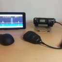
first of all thanks for the nice image. That fits 100% with my portable ideas. Since i got the second RTL stick I start to do my tests with two RTL sticks placed in a small box depicted below.
But i was not able to run the drift control. After clicking the lock menue the colour is still red and there is no value for frequency drift visible. I repeat the calibration procedure several times with no success. Where can i check if the second stick is working well with no connection error.
Could it be that i have an old image (can't find Fldigi at the current Image).
Maybe i did something wrong in generell.
Thanks in advance for your answer.
Kai
I am preparing updated version with some bug fixes, improvements and Fldigi preinstalled/preconfigured (for digimodes via QO-100) ...
-

Hm.. let's do some math. The offset is around 10cm to fit next to the LNB and the lever arm (focal length) of a f/D=0.7 is 80*0.7=56cm. So the angular offset is arctan(10/56)= 10 deg.
According to G3RUH (60cm dish) a 60cm dish has a -3dB beamwidth of 16 deg, so 8deg offset is -3dB. The 80cm dish should be more focused and we are 10 deg off, so I would at least expect -5dB or ca. 1/3.
So your quoted 8-10W fits nicely with the 2-3W I was hoping for with a perfect setup.
Achim, i had the same antenna directly in the focuspointpoint before and I was not able to measure the delta in uplink between solution-in-focus and solution-out-focus. Maybe (if time) i will analyze it with FEKO and present the graphs here to now the exact values. To measure this via the transponder is difficult.
The only dis-advantage was the decreasing of the downlink signal with in-focus but this was expected before.
See both solution depicted below.
-
How much power do you run? I tried something similar with 20W and was less than impressed by the resulting signal on the transponder. The squint angle between LNB and helix is probably too large at my side.
I use 8-10Watt at the Helix connector and it works well with strong signal and 80cm Pollin dish. For S-Band the focuspoint is not so critical in compare to Ku-band. I optimized it a little bit by downtilt the Helix towards the dish center. Same signal strength in compare to a WLAN barbecue grid antenne i used before.
-
And here is my final version after several optimization. Helix in front of the LNB feed gave me to much losses (arround 5-6dB). With mounted solution above the LNB no degradation measured in downlink and the uplink signal was increased a little bit by downtilt the Helix towards the center of the dish. The return loss of the helix was optimized and tuned with a mechanical C (piece of aluminium) nearby to the feedpoint of the helix. Finetuning by moving the aluminium piece. Max. return-loss gave me - 26dB.
The remaining open point is to make that water/winter resistant.