

Some new work has been done recently.MRF21085 13 cm PA OUT: 40W
Traditional architecture upstream and downstream frequency converter.Can work at UP/DW 28/145/430
Some new work has been done recently.MRF21085 13 cm PA OUT: 40W
Traditional architecture upstream and downstream frequency converter.Can work at UP/DW 28/145/430
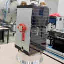
With the coming of winter.Outdoor aerial need to quick and convenient way.I put my 60 cm antenna modified for ease of use.
LNB support bar can be folded, it is more convenient to transport and use and fast
The last piece of PA carefully debugging.Output 20 w +, including frequency converter in a waterproof container, CATV cast aluminum.
May be able to increase a through feeder power supply scheme.24 v3a power supply...
Now I have 4 sets QO100 earth station equipment (frequency converter + pa), I will send them to the interested in QO100 HAM friends around me.As soon as possible to help them more in the repeater.
I suddenly realized that maybe the problem is the LNB output of 28.55 intermediate frequency signal feedback to the LNB pll_ref, if use a separate ref cable and if cable may be able to solve this problem
I have done a similar test.10 w can work in the digital mode.
Here is a test video
My friend put forward a request.On the recommended frequency converter using 28 m intermediate frequency.I did some test for UP2400 seems to be no problem.But the rx ran into trouble.LNB ref no response signal of above ref 26.5 M+.
28.55 up2400.05 it looks good
The test environment.Simple frequency converter + 1 w PA
Someone made similar test?My frequency calculation:
RX (10489.55 28.55) / 390 = 26.8230xxxx
28.55 + 2371.5 = 2400.05
May increase the input level value, reduce a little bias voltage...Mrf21045 seems to be very not easy damaged, I never burned in all of the tests.
For me is the most commonly used;Well, my English is not good, so don't understand too much what you said...I can only try our best to exchange callsign QTH signal report 73
:}
For mrf21045 in 2.4 g I have 12 db gain satisfaction.After all, is beyond the frequency range of his work.The actual uplink signals the diagram below.
For mrf21045, my bias voltage is 2.7-3.0, 0.55-0.9a at 24v, and 42DB is output when 30DB is input
@ IS0GRB Thank you. I already know how to operate it.:)
How is duplex operation achieved so you can monitor your signal on the transponder?
QO100 WEBSDR
The initial idea comes from a block diagram of PE1CKK
I love the simplicity of the design.So let's start.
PCB integrated ADF4351 Attiny13 PTT automatic detection LNB reference duplex 2.4g mixing output 3-5db
2.4G 1w PA E5+SF2124+AH1+FLL357. IN:-5DB OUT:30DB
2.4G 10w+ PA Gain:11DB
Put them together.
It is very convenient to use, only need output connected antenna and LNB.With radio only one feeder is needed.It can be placed near the dish antenna to reduce the loss of 2.4g.
I open source all the material and anyone can use it to improve it.Thanks to all my friends who helped me...
Eshail2-QO100-Simple-Frequency-Converter PCB
73
BG0AUB
PA1EW I read your article carefully, there are a lot of harvest.
Do use five minutes late out houses (window) to do the uplink test.The helix antenna works well.I think he has 16 to 18 db gain.Thank you for all the people who help me...New idea is: may challenge without DISC antenna, the use of LNB with what other antenna QO100. Personally, I think this is very difficult, because 60 cm DISC in 10 g gain about 35 db
PA3FYM We're waiting to hear your story...
I tested the 20w+ drive antenna, and there was no heat in the carbon fiber support rod that was conducting with the reflector... : -)
Coil is yellow in glass fiber board, used to keep the spiral shape
In order to make up for a lack of overall rigidity, fixed with a carbon fiber tube in the middle.
Now I have the carbon fiber tube and reflector and reliable connection (conductive carbon fiber tube)
Using the computer design parameters

This article I published around 20 years ago.
Don't have it anymore (because the server -at that time- doesn't exist anymore) but somebody saved it for later use.
20 years ago,When I was 18 years old... ![]()