Posts by dm4im

    Hi there,

    I don't know when and why it happens, but i too see some wiggling now and then. My setup is a RTL-Stick and a homemade GPSDO with 25MHz OCXO for the LNB , this rules out your Leo Bodnar and Pluto for the cause. To check for instabilities, listen to the upper tone on the lower cw beacon (or lower tone on the upper beacon) when the beacon transmits a straight tone. If it whines while the vertical line in the Geo-Beacon display zig-zags, you have the proof there is some instability. 5-15Hz whine is easy to hear. This won't tell you where the instability happens, but there is a chance sdr console displays quick changes in frequency that don't exist.

    Maybe mixing with other signals on the satellite? This might have an impact on reception and make the algorithm display weird things resulting in zig-zag. My 2 cents.

    73, Martin

    YMMV

    Moin.

    Mache die PA stromlos und drücke die PTT. Problem noch da?

    Wenn ja, ist es ein Problem mit der Konfiguration der sdr-console. Vielleicht MUTE aktiviert?


    Ich bin nicht sicher ob MUTE im Zusammenhang mit dem Pluto überhaupt angeboten wird.

    Viel Erfolg.


    73, Martin

    Welcome to the club


    I kindly disagree with Martin: if you setup a 1.5m dish you should try to get out the optimum of it. Otherwise it is a waste of
    time and material ...

    I agree. I just wanted to point out, that even with a cumbersome antenna, you will have good results with a dish that diameter. My first antenna was the 4 element yagi pointing into the dish , the 2nd was a linear polarised patch feed without waveguide for the lnb and the one i'm using now is a poty . Learning by doing, improving over time. It is more important to have a clean signal, may it be not so strong. The LEILA triggering signals are for later, and even those are clean, if you overdrive NONE of your gear......

    Regards

    Martin

    P.S. : I don't encourage anyone to trigger LEILA.

    I will need some attenuation before the upconverter, minimum output on my TS2000 is 5 watt - and the upconverter needs between 1 and 3 watt, output alone should be a max of 200mW, so i need the amplifier, i am counting on being able to turn down the output power directly on the DXpatrol mk4 upconverter using the pwr adj, and in doing that limit the output from the amplifier.

    I don't buy that. If that is true, you must convert a max. of 2.8W into heat to have 200mW output. Meaning the upconverter has negative conversion gain (in the range of ~ -10/12dB) . If you have measurement gear for 2.4GHz it is of great interest what really is going on.

    Set your TS2000 to a good , strong audio , the audio you like to have when you talk on 2m or shortwave. Do not touch audio settings for the the following measurements. Set TS2000 to minimum available power with it's power potentiometer. Now insert a 20dB attenuator , this should result in 50mW output. Connect your upconverter and measure the output , while you adjust the power adj potentiometer on the dx-patrol board. If you don't get 200mW out, turn pwr adj to it's highest setting , insert about 15 or 13dB instead of 20dB, for ~200-250mW input to the upconverter. Repeat measurements. I'm sure you will reach the maximum output power with less than 250mW input.

    Many dx-patrol users say , the vox circuit will not work properly with low input power, but most of them adjust output power of their radios by reducing mic gain and compression. Which i believe is the wrong way.


    Regards,

    Martin

    P.S. : I may be totally wrong.

    It is always beter to attenuate the INPUT TO THE Upconverter on the radio side , not the output after the upconverter . This will result in a clean signal without nasty sidebands. You should check if that is enough signal strength. If not, you still can kick in the amp. You will need attenuation ahead of the amp, I'm sure.


    73

    Pic 1: Poty in the holder where normally the feedhorn of the original Hirschmann feed is located. The original feedhorn sits snug against the aluminum holder, but because the poty reflector diameter is 100mm, the 3 feed arms prevent it from being placed snug against it. The distance is 3-5cm , i think.


    Pic 2: Reveals the reflector size and why you can't push it closer to the focus position.


    Pic 3: To compensate for the poty not sitting in the focus, i liftet the 3 feed arms a bit above the dish with bolts and nuts. Observe the left side of the picture where the arms are mounted on ( ABOVE , that is) the surface.


    I'm pretty sure this still isn't the best position, but my signal is loud enough even on very low power and i can hear pretty well. Before i lifted the feed arms a bit up, the signal was loud, but afterwards I had to lower power by at least 4-6dB. To this date, i do NOT know my output power, maybe 2-3 Watts , minus the attenuation the 8m long cable from the amp to the antenna introduces.


    73, Martin

    Hi,

    with a dish that size, the antenna doesn't really matter much unless you plan to run very low power or datv.

    I use a 150cm PFA and got very good results even with the 4 element yagi the manufacturer of my upconverter provided as a free gift, pointed in the dish.

    With a POTY or Helix in the right spot (focuswise) you need to keep the power low (wich is good when you use dx-patrol, because they tend to overdrive everything)


    73, Martin

    Verwendest Du den Adapter von kab24.de am Kuhne 2424!?

    Nein, am K3. Ich habe oben gelesen, dass Kuhne wohl einen höheren Pegel erwartet, als von modernen Adaptern bereit gestellt, deshalb kann ich nur für die generelle Funktion sprechen, und da hat sich der FTDI-Chipsatz bewährt. Laut https://ftdichip.com/products/ft232rl/


    arbeiet der Chip aber mit nur 5V . Vielleicht findest du einen mit 10V. Sorry für die Verwirrung.


    73, Martin

    GM,

    USB<>RS232 Adapter mit den Prolific Chipsätzen verursachten in der Vergangenheit immer wieder Probleme. Der Hersteller hat in seinen Treiber eine Prüfung eingebaut, die feststellt, ob der Chip ein Original oder ein Fake ist. Wenn es ein Fake erkennt, verweigert der Treiber den Dienst. Selbst wenn man vom Hersteller des Fake-Adapters einen Treiber downloaden konnte, hat man nach dem nächsten Windows Update ein Problem, weil Windows den Fake-Treiber mit einem Original- oder Windowstreiber überschreibt. Google danach, du wirst jede Menge Hits haben. Elecraft z.B. hatte viele Beschwerden ihrer Gemeinde deswegen und auf FTDI umgestellt.


    Adapter mit FTDI Chipsätzen haben dieses Problem nicht .

    https://www.reichelt.de/usb-2-….html?&trstct=pos_2&nbc=1

    https://www.reichelt.de/usb-2-…html?&trstct=pol_11&nbc=1


    Ich benutze seit Jahren

    https://www.kab24.de/computer/…2rl.html?cache=1675683097


    plus ein USB- oder Sub-D-Verlängerungskabel.


    Hier der Link zur Downloadseite des Chipsatzes:
    http://www.ftdichip.com/Drivers/VCP.htm


    73, Martin

    Hi,

    if you use 24MHz, you will find the center of the downlink passband on 10489.750-(24*390)= 1129.750 .

    If you use 25MHz, you will find the center of the downlink passband on 10489.750-(25*390)= 739.750.


    The 24MHz reference lets you receive the DATV transponder on a normal unmodified Sat-RX ; you can receive the beacon and some other individual signals.

    The 25MHz reference does not allow that, because sat-RXes do not cover 740MHz.

    If you want to receive with a normal 432MHz rx , you use a reference in the range of 25,78xxxMHz

    Some even receive directly on 2m band.

    If you use a rtl-stick or other sdr device for rx, it is not important, what reference you use, as long as the device can receive the resulting frequency.

    Identify the built-in crystal by checking the LO frequency printed on the plastic cover, 9750 means it is 25MHz.

    25*390=9750 , but it will also work with 24.xxx or 25.78xxx MHz.

    Edit: The description for the lnb from the link you provided says 9.75GHz. Voila'

    73, Martin

    Hi,

    you may install Virtualbox , a software for virtual operating systems, on your Win10 PC , then install and run a operating system known working with HDL_ANT inside this software.

    I use virtualbox on windows computers (and linux computers) to make (older) windows versions run software i can't get to run on newer windozes or linux.

    The screenshot above shows Win7 32bit in the background and Win10 64bit in foreground both running simultaneously on my linux pc.

    73, Martin

    Hello,

    This looks like an empty transponder with the beacons switched off. FT8 is still there, so power is available. Make a screenshot of the strong signal on 10489.300. I see no signal on my rx there, so maybe the websdr you are using receives it from a local source. Is it always there? Which websdr have you been using and what time?

    73, Martin

    Moin,

    könnte sein, dass du auf Unverständnis stößt. Das Thema hatten wir vor mehr als 2 Jahren als Diskussion über den Satelliten und die meisten Mitdiskutierer wussten gar nicht, wovon ich spreche. :)

    Offenbar passiert das nur mit RTL-Sticks, die Pluto-Nutzer kennen es nicht. Ich habe dieses Problem auch und habe es so gelöst:

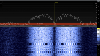
    1. Frequenzmarker für die Mittenfrequenz der PSK-Bake erstellen, 10489.750.

    2. "Einfangautomatik" im Geostationary Beacon Fenster ausschalten und mit dem Zoom Schieber rechts in der Spektrum-Anzeige über dem Wasserfal so weit einzoomen, dass die Bake eine guten Teil des Bildschirms füllt.

    3. Im Wasserfall immer LINKS vom - und ganz dicht dran am - Frequenzmarker Rechtsklicks ausführen, bis der Marker in die Mitte der Bake zeigt. Wahrscheinlich ist nun die Bake aus dem Fangbereich im Geostationary Satellite Beacon Fenster gehüpft. Hier muss man durch einen Linksklick auf das Bakensignal nachhelfen.

    4. Auszoomen bis die obere und untere Bake gerade noch in das Fenster passen, oder nach Gusto . Die PSK-Bake sollte nun genau in der Mitte sein, der angezeigte Frequenzversatz nahe 0 und sollte so bleiben ( plus/minus Doppler über den Tagesverlauf , Frequenzdrift des RTL Sticks beim Aufwärmen bzw. durch Zugluft, Stabilität der Referenz für den LNB).

    5. Einfangautomatik wieder einschalten , oder man hat einen genauen GPSDO und einen Stick der nach dem Aufwärmen wenig driftet, dann kann man es auch ausgeschaltet lassen.

    6. Zukünftig Rechtsklick vermeiden, oder starte bei Punkt 2. ;)


    Ich habe mich dran gewöhnt und sehe es als ärgerlich, aber nicht als Ausschlusskriterium für sdr-console an. Vielleicht kann jemand den Software-Autor bewegen, das zu reparieren.

    73, Martin

    Moin und hny,

    nach genauerer Untersuchung: vanessa ist eine Version von Linux Mint, aber kein Betriebssystem für raspberry. Deshalb die Fehlermeldung. Das script will libpulse-ocalm installieren, aber dein raspberry weiss, dass das keine Version für ARM-Prozessoren ist, deshalb die Warnung. Das Gleiche gilt für libpulse-ocalm-0.1.2-1+b2. Versuche besser nicht, das script so umzuschreiben, dass es für dein OS passt. Das kann man zwar machen, aber wer weiss, wieviele unerfüllte Abhängigkeiten noch folgen . Am Ende artet das in richtig Arbeit aus.

    73

    Hallo,

    versuche ein Upgrade des Betriebssystems auf vanessa oder installiere neu. Wenn das nicht hilft, solltest du die Fehlermeldung in die Suchmaschine deines Vertrauens eingeben und schauen, ob du was findest, wie du eine Lösung erzwingen kannst. Es kann aber passieren, dass erzwungene Konflikt-Lösungen das System beschädigen und oft wird davon abgeraten.

    V1.73 bringt keine Verbesserungen gegenüber 1.72, nur ein bisschen Kosmetik im Falle eines Crashes oder beim Beenden. Ein update lohnt m.E. nicht wirklich. Vielleicht muss man noch ein bisschen warten.

    Quote

    V1.73 ...April, 2 2022 ... when restarting: uses last RX/TX qrg. This makes it easier to continue a QSO if the software was stopped or crashed.

    V1.73a...November, 16 2022 ... extended the install script for the ubuntu version vanessa. The TRX is the same as 1.73, just the installation has been extended.\

    73, Martin

    Hallo,

    wenn das tatsächlich fast die gleiche Schaltung wie bei DJ0ABR ist, dann kann man ja schauen, ob 5V und 28V vorhanden sind. Wenn beim ansteuern der PTT der Ruhestrom nicht ansteigt, ist vlt. nur der N-Channel MOS-FET IRLML2502BPF (oder der dort für das Schalten der PTT verwendete MOS-FET-Typ) , defekt. War bei meiner DJ0ABR-PA jetzt schon 3 mal so und der einzige Grund für Ausfall bisher. Ob die 28V und die Spannung für den Ruhestrom am PA-Transistor ankommen, kann man m.E. in der Nähe des PA-Transistors mit dem Voltmeter prüfen.

    73, Martin