Posts by M0VKK

    I guess they may vary - but I have two and they measured 11.6dB and 12.4dB at around 2W out.


    The articles and postings I've read tend to agree with this - 12dB is the most common reported and the highest I've seen was 14dB, but that was with the supply mod and I think the link mods too.


    I have a 4W model which gave a bit more gain, but less output.

    That's about an average gain for those amplifiers. There is nothing wrong with it I'm afraid.


    As mentioned by Johannes above, you can bridge the input and output switches to get a dB and a bit more gain.


    Most people run them with closer to 23dBm in to get full output. These amps get a bit of a bad press for splatter, but in reality they will run pretty cleanly up to 3W out - the difficulty is that people are using preamps with a P1db of 20dBm as those are the only easily available ones from ebay etc.

    I think PEP is the correct method - not ERP.

    ERP is the equivalent output compared to an isotropic radiator. The power into the antenna never gets to be more than the PEP and the total power in the beam from the antenna can never get to be bigger than the PEP assuming the beam is the same width as the dish.


    I probably didn't explain that very well....


    With a 1m dish the area is 0.78m^2 so assuming a perfect dish the power is going to be the PEP/0.78 W per m^2

    Whilst I haven't experimented with mine any more as I'm still tied up at work and will be for the next week or so, someone on facebook (James smith) has tried the same amp and said


    'Andrew amplifier module from Bison Electronics tested at 24 volts biased at 1A per device gives 55 Watts out for 900mW in at 2405MHz with no tuning yet. It will be the driver for my next big amplifier but it is already as good as a spectrian! Supply 6.4 amps for 55w out 3.8A for 20w out 13.6dB gain and it will also work on 32 volt supply'.


    So his results look pretty much in line with mine.

    Ok more progress - but not good news! I roughly built the amplifier into a case for testing - and tried running it from the pluto with DATV. The DATV output from the pluto was about -9dB so it was only putting out a few watts. I ordered another +18dB amplifier for the input and was testing it and it happily gave an estimated 40W out without getting too warm and was pretty stable. I ran it for about half an hour like that and could easily receive 500kbs with a good MER -so the signal looked clean.


    However - because I was experimenting there was no screening on the preamplifiers or driver . I disconnected the input but forgot to switch the PTT off. It broke out into oscillation and drew about 20A at 28V for a few seconds and one of the output devices died.


    The other device survived and I could limp out about watts - but the second device couldn't be set to a good idle current and now is only class C! Surprisingly the output xinger survived!


    I have a spare output module so I will fit that at some point - however work requirements mean I'm not going to be able to repair it for the next two weeks. I also need to replace the 28V-12V regulator as I forgot the extra draw of the extra preamp took it out of spec and it got very warm!

    I had one of those transverters and in the end I threw it. You can improve it by putting a large metal block on the oscillator and then fill the case with cotton wool. It does stop the worst of the drift. I tried inserting a GPSDO local oscillator in instead, but it didnt seem to like it much.


    Sadly there aren't many good and cheap transverters. I have an Electraft 432 one and it isn't all that good either.

    I promised an update this weekend. Sadly not much to tell. I built it all into a case and wired it up and built a new power supply. I also ordered a 40dB directional coupler which had a short in it and blew my power meter up as soon as I ran it up.

    Those are about the main reasons I chose the board. The devices being rated at 2.2GHz gave a much better chance of success that the ones that are more suited to 2GHz. The Zs was pretty flat over the operating range and so could be assumed to stay reasonably flat over the extra 10% range. The output looked a little bit more tricky and I assumed I would have to snowflake quite a bit to get a good match . Which is the reason I'm a bit suspicious of my efficiency measurements, I was guessing that it would be closer to 20-25% without adjusting.


    As you say the xingers are specified up to 2.3GHz - but looking at the curves and extrapolating a bit indicated that the loss at 2.4GHz wouldn't be too bad - as long as the power was kept to a reasonable level. Also I found a replacement Xinger the same size rated for 2.4GHz that only costs £3 which could be substituted if required and rated at 150/200W.


    Model XC2500A-03S


    Sadly I'm unlikely to get any more time to test until next weekend.

    dg0opk To be honest I hadn't noticed until you pointed that out. I suspect that the stripline/capacitor forms the load. Too much mismatch between the two devices could cause that to fail quite quickly. I might cut that track and replace it with a 20W 50 ohm resistor.

    I'm also going to get my 20dB coupler tested, it's a cheap Chinese one and I'm suspicious about the efficiency I'm getting. It can't be that easy to get this amplifier to work. I also changed the shunt input capacitors whilst initially matching and now I'm not sure I put the original ones back....


    I've got another one of these on order and I will test it properly next time. I just had two hours spare on Saturday morning and was in a rush to see if I could get it to work.

    I was aiming for 40w for the pair so I'm happy. At the price I can parallel two sets if I need more. I have 2.4m dish so I'm not looking for a lot of output. Oscar 100 is just a diversion before I get back to EME which is my real love.

    I received my amp from poland on Thursday and just managed to put it on a heatsink to test it.


    I got the 'RF linear amplifier with - 2x MRF7S21110HS - 2,2GHz' from bisonelectronics for £29.65 +£4.24 postage


    I did snowflake it a little putting thicker input lines to improve the match - but then took them off to test it in its bare state properly so I could get a baseline for improvements.


    I connected it up to 28V and set both bias to 1100mA via a pair of simple regulators and then adjusted the two input trimmer capacitors for a reasonable SWR ( about 1.7:1) and then started measuring. It's a bit of a fiddle to adjust the input caps as they seem to work in opposite directions. With a small signal in (100mW) I adjusted them a little further so the drain currents on both were about balanced - its difficult to match properly when there is a zinger in the input dumping any mismatch.


    With my capacitor settings I got a 1:1.2 match @2.2GHz , rising to 4:1 at 2.3GHz and back down to 1.7:1@2.4GHz


    Much to my surprise these are the results I got:


    Gain 13dB @ 40W out

    Efficiency at 40W 28%


    I have no idea what the max CW power output is as it got up to 80W before I realised that I was in danger of blowing up my dummy load which is only rated at 50W and ought to stop before I damaged something.


    Excuse the mess in the photo - I only had a couple of hours free so I thought I'd just rush in and clear a few inches of desk space to give it a quick try.


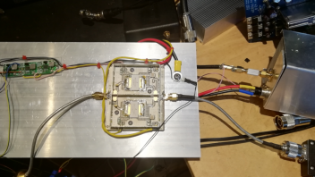
    So it would seem this runs quite nicely without any snowflaking required. I've bought another one in case I blow this one up while testing.


    Edit: The output combiner is only rated at 105/145W and whilst the p1dB of each device is 110W I suspect it would blow up if I pushed it any harder than 80W. I cooled it with 2x 10cm fans and the temperature stayed about 46 degrees when testing.

    I've got a triax 1.1m too. I just did a test and I can see the NB transponder beacon at +/- 5 degrees.


    However it becomes more difficult if you dont know exactly what frequency to look at because of LNB drift. I started with a 60cm ex sky dish to find the frequency first and then moved it to the triax dish.

    Thats a relief, I wish I'd bought one now!


    I'm sorry if I caused you concern - I just assumed the BLD6G22L-150 and BLD6G22L-50 would have been similar devices given the both have the D for doherty!


    The only information I could find for the -150 was as below - so the Idq you measured of 1340 looks to be in the right region. Apparently the module was rated at 60W (linear) in the sales literature.


    I took the pin numbers on the diagram to match up with the pins shown on the device


    This is just curiosity for me as I have bought a different board now!


    Also:

    The BLD6G22L-50 and BLD22LS-50 incorporate a fully integrated Doherty solution using Ampleon’s state of the art GEN6 LDMOS technology. This device is perfectly suited for CDMA base station applications at frequencies from 2110 MHz to 2170 MHz. The main and peak device, input splitter and output combiner are integrated in a single package. This package consists of one gate and drain lead and two extra leads of which one is used for biasing the peak amplifier and the other is not connected. It only requires the proper input/output match and bias setting as with a normal class-AB transistor.

    I was looking at the BLD6G22L-50 datasheet


    which looked like the 90 degree shifts were built in to the BLD. I assumed the -150 was just a higher rated version.


    To be honest - I'm out of my depth here - this isn't my area of expertise so I'm just guessing - that's what I like about this hobby - always something new to find out about.

    I don't think I am brave enough to try that module. Although it is multistage with a lot of gan, I don't think I am experienced enough to try to snowflake a multistage amplifier at this point- and the inbuilt doherty worries me as I hate not knowing what is going on in a chip - I can't adjust the internal lines!


    I decided to opt for the dual MRF7S21110HS board that he has on offer. Probably a little less power - and a lot less gain but hopefully easier to work on!