Posts by DD1US

    Hi Elmar,


    I heard from several OMs having trouble with VB-cable and hsmodem, even though VB-cable worked with other applications.


    If you have a chance, could you please try VAC ? Pleae make sure that VB-cable and VAC are not running at the same time.


    I am using only VAC and that works fine.


    Kind regards


    Matthias


    http://www.dd1us.de

    Hallo Namensvetter,


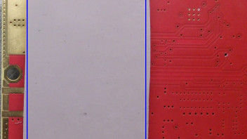
    vielen Dank für die Bilder. Also die Größe der Pads würde ausreichen, um sie zu stacken und die beiden PAs und das Schaltnetzteil darüber ausreichend zu kühlen. Bei Dir wird unten etwas Wärmeleitpad fehlen, d.h. Du brauchst es nicht wegen der Schraube auszuschneiden. Das sieht dann etwa wie folgt aus: blaues Rechteck in Bild 1.


    Alternativ kannst Du sie auch nebeneinander auf die Unterseite der Platine kleben. Dann ist der Wärmewiderstand nur halb so gross und Du belastest die Platine auch mechanisch gleichmässig, wenn Du sie mit Schrauben befestigst.


    Nun kommt es aber auch darauf an, ob Du die Platine auf eine grosse Platte schrauben willst, dann wirst Du die 3mm brauchen damit Du die SMA-Stecker montieren kannst. Falls Du die Platine auch einen Kühlkörper oder Metallklotz montierst, der gerade so gross ist wie die Platine, dann wirst Du mit den SMA-Steckern keine Probleme haben denn die SMA-Buchsen ragen ja dann seitlich über den Kühlkörper/ Metallklotz heraus.


    Ich habe das bei mir schon einmal so gelöst: Platine, darunter Wärmeleitpad, darunter ein Kupferklotz ca.5mm dick, das dann alles auf einen Aluminiumkühlkörper geschraubt (siehe Bild 2). Das hat super funktioniert. Dank des dünnen Pads und des Kupferklotzes bekommt man die Wärme wunderbar weg.


    Falls Du den Weg der gestackten Wärmeleitpads wählst, dann solltest Du zwischen Platine und Kühlkörper 3mm Abstandshülsen verwenden. Damit vermeidest Du dass sich die Platine bei anziehen der Schrauben durchbiegt und die SMD-Bauelemente beschädigt
    werden.


    Viel Erfolg bei der Inbetriebnahme.


    Viele Grüße


    Matthias


    http://www.dd1us.de

    Hallo Matt,


    normalerweise sind die Wärmeleitpads knapp über 3mm dick so dass sie nach dem den Andrücken 3mm dick sind.

    Um Verspannungen und damit Schäden an der Upconverterplatine zu vermeiden ist es wichtig, dass der Upconverter
    entweder mit einem ganzflächigen Wärmeleitpad unterlegt wird und dann die Schrauben gleichmässig angezogen werden
    oder dass man Abstandshülsen mit einer genauen Länge von 3mm verwendet (mit den oben genannten knapp über 3mm
    dicken Pads.


    Theoretisch kannst Du auch dünnere Pads verwenden, allerdings bekommst Du dann je nach Deinem Aufbau Probleme
    die SMA-Stecker auf die Buchsen schrauben zu können. Je dünner das Pad ist desto geringer ist der Wärmewiderstand.


    Wann hast Du denn diesen Upconverter gekauft ?


    Gruss


    Matthias


    http://www.dd1us.de

    Hi Flo,


    sure I remember your programming skills and therefore I asked you seriously to contribute to the project.


    As I wrote Kurt is presently devoting all his time in this project.


    There have been problems getting the Highspeed Modem running on all platforms and Kurt is adressing this first.


    Once this is stable (v0.72 is in my opinion a good candidate) additional features might be added.


    Kind regards


    Matthias


    http://www.dd1us.de

    Hi Flo,


    please be patient. Kurt has worked a lot in the last week to fix some soundcard related issues.


    Do do not believe how many hours he has spent in this development.


    But as he is making the sourcecode free available maybe you want to join and do some work yourself on the missing features you are asking for ?


    Kind regards


    Matthias


    http://www.dd1us.de

    Hi Stefan,


    no, actually you can also use 50 Ohm connectors instead if the 75Ohm connectors if you like.


    The NB-LNA in port is actually already matched to 50 Ohms: the 3 resistors are a 3dB attennuator to make sure,
    that the following filter (which is a 50 Ohms filter) is properly matched.


    On the WB input you could improve the circuit slightly if you exchange the 75 Ohm resistor R25 by a 50 Ohm resistor
    or just solder an additional 150 Ohm SMD resistor parallel to R25.


    Kind regards


    Matthias


    http://www.dd1us.de

    Hello,


    here are some additional details on the AMSAT-DL Online Symposium 2020 and Virtual QO-100 Usermeeting


    The AMSAT-DL Symposium will start at 09:00 CEST (0700z) and will be followed by the QO-100 virtual user meeting starting at at 17:20 CEST (1520z) on the narrow band transponder.


    You are invited to ask questions during the Symposium and announce your participation for the Usermeeting via WB tpx chat on [1] (please set you nick Name with "/nick N0CALL" to your callsign) or via the YouTube chat on [2]. Please note that you need a registered Youtube account to be able to enter your questions in the chat window of Youtube. This is not related to our streaming but a general requirement.


    We will stream the Symposium on the wideband transponder of QO-100 with the following parameters:

    Callsign DK0SB

    Frequency 10494 MHz

    Symbolrate 2Msps

    Modulation QPSK


    During the Symposium we will address the questions after each presentation to the presenters (we may not be able to ask all questions as we are limited in time).


    With respect to the Usermeeting we will collect all the pre-registrations and call you one by one on the narrowband transponder at 10489.830 MHz using the callsign DK0SB. As soon as the list is processed, we will go split and listen approx. 10 up for any other users.


    [1]: https://eshail.batc.org.uk/wb/chat


    [2]: https://www.youtube.com/watch?v=QNRahMn2dYE


    Kind regards


    Matthias


    http://www.dd1us.de

    Hallo Thomas,


    nein ein Schaltregler ist ein DC-DC-Wandler.


    Hallo Roland,


    Deine Rechnung oben hinsichtlich der Berechnung des Intermodulationsabstandes ist grundsätzlich ok.

    Wie man aus den Messungen im AMSAT-DL Journal sieht ist der Übergang des mehrstufigen Verstärkers

    vom linearen Bereich zum Sättigungsbereich sehr "weich". Damit dürfte die Formel oben nicht mehr

    anwendbar sein. Es ist also wohl eine echte 2-Tonmessung nötig um den Intermodulationsabstand zu

    ermitteln.


    Gruss


    Matthias


    http://www.dd1us.de

    Hello Geri,


    reading the thread again I guess you were referring to the Pluto and not the Lime.


    As far as I know the feature I described above is only available for the Lime.


    Sigi has described in the SDR-Betatester-Group a way how to do it with the Plut. More complicated but also possible.


    Kind regards


    Matthias


    http://www.dd1us.de