Posts by SV1BDS

    Hi, a question for anyone can help. When I connect my dual output directional coupler to AD8302 meter I can not get right measurments execpt I connect 2 same value 10 dB attenuators. Note that with and without attenuators dBm values was inside dynamic range of AD8302. Without attenuators when I terminate each output with a dummy load I see at the other port correct values. But when I connect the AD8302 the values are changing. Note that AD8302 PCB has proper 50 ohm load (52.3 ohm R) as datasheet advises. It is not a AD8302 read error as I put a -20 dB probe at each port and I measure values similar to AD8302. Can anyone can give an explanation of this ?

    Hi ok scheme that you sent me as a correct value for R2 and R3 resistors? , meanwhile I mount the circuit

    73 Roberto

    R2 is 0 ohm (replace with wire) R3 is 1 kom. Also power the 2*16 LCD with 1 kom from 5V at pins 15,16.

    If you have ATMEGA8, HC164 and 2*16 you can test it providing 5V and 1.8V at VRef. If you put a var R from 1.8 V you can simulate the voltage from AD8302.

    Note that sometimes when power up the LCD it does not reset properly and you just close and open the power. Also sometimes the LCD display wrong but then it refresh.

    yes ok i have a spectrum analyzer hp8565a, qello with ad8302 it is useful to take it to the garden to test the antenna this point should I create the right directional coupler that I see on your site?

    Yes build the directional coupler. May be it is better to use SMA for coupled outputs and N for transmitter and antenna. If you have two semirigits with connectors use them as it is.

    Hi Roberto, I tested with my directional coupler and it works as soon as you put at least 10 dB attenuators (propably same value) at both inputs. You can use the cheap spectrum analyzer with tracking from eBay and have SWR vs frequency !!! For this solution your single coupler is enough. With the AD8302 you can measure your transmitter SWR combined with your antenna, with analyzer you measure only the antenna. NOTE that AD8302 has 0 dBm max and min -60 dBm. So if you have for example 1 W at 2.4 which is +30 dBm and the coupler has for example 20 dB coupling you need at least two 20 dB attenuators to be in the safe side. From the other side if you use too litle power for SWR measure consider that you need at least -40 dBm of forward power and be able to measure SWR (20 dB more than -60dBm lower limit). Is that clear for you ?

    Hi Roberto, only with this directional coupler you can not use the AD8302 as it is have only one output.

    Do you have any semirigit cables? You can easy build a similar to mine with two outputs.

    I have not tested this setup but I suppose it will work. I can make the test to be sure it works.

    power supply

    18650 charger and protect

    the reset pin has to be pulled up with

    10 kom without a button.

    the adc2 circuit is ok.


    One correction : the circuit of lcd driver is not connected to adc0 and adc1 !!! the 1,2 pins of the 164 goes to pin 14 of the ATMEGA8 and pin 8 of 164 go to pin 15 of the ATMEGA8.


    At the charger border I changed the pcb leds with a common anode red green dual led.


    What direction coupler do you plan to use ? If you are outside you will have wrong swr or burn the AD8302. If you are not sure pls tell me. It is critical that you must be inside dynamic range of AD8302.

    SWR indication displayed only in one direction of inputs. If you do not see SWR just reverce inputs. reverse if you do not see negative gain.

    AD8302 pcb has internal termination R so you just connect them to coupler.

    Hi, can you measure the voltage that controls the frequency of the gpsdo oscillator with the scope to verify that it does not have 800 Hz ? Also with an HF receiver and an RTL stick see if the 25 MHz has sidebands of 800 Hz? Also for 10 MHz of gpsdo. Also check with the scope the power supply line that is clean.

    WARNING: the resistor divider on the 18650 will discharge the batt if not cut by the main switch


    batt res div is: 4.2V - 330K - 220K - GND


    db on ADC0

    phase on ADC1

    vbatt res div on ADC2


    AD8302 display 16x2

    1234567890123456

    Gain SWR Phase !

    +xx.x x.x xxx°


    the '!' prints when low batt


    avrdude -p m8 -c usbasp -U lfuse:w:0xE4:m (8 MHz int clock)


    Also 10 Kom pull up at Reset pin.

    Two 10uF MLCC at each side of power of ATMEGA8.

    VREF of AD8302 goes to AREF of ATMEGA8 , add a 100 nF cap

    2*16LCD driver IC is 74HC164


    I use a 2.5-4.2 V to 5V PCB from eBay for powering the system via a 18650 and a charger-protecting PCB also from eBay.

    iw5bsf any questions ?

    Hi, as I try to improve performance of my QO100 station setup I realize that some topics are important. This is a writedown in order to help anyone in areas for improvment and for me if someone has something to add.


    - feeder performance

    - power output

    - CW signal vs CW beacon in dB

    - Tx audio quality

    - Tx & Rx frequency accuracy

    - Tx & Rx frequency stability

    - Tx at same Rx frequency

    - Rx while Tx

    - SNR of CW beacon

    - IMD Tx performance

    - 13.8 V operation

    - Pwr & SWR indication

    - SWR of Tx antenna

    - Tx key down time (how many time can stay in Tx without be burned ...)

    - no self oscillations

    - dBm of parasitic Tx

    - SWR protection

    - same antenna for Rx & Tx

    - degree of homebrewing

    - weather conditions proof

    - mechanical conditions proof
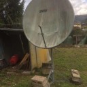
    - roof 2.4 Ghz unit

    - length & loss of pigtail (cable from Pa to feeder)

    - size of Rx & Tx antenna

    - power output control

    - spectrum view of Rx

    - total signal performance of Tx (power, pigtail, feeder, Tx antenna)

    - portable capability

    - PC audio connection

    - modes supported

    Hi updated roof box. Lo SMA chassis connector was desoldered and resolded. The IMD is improved after this mod. May be this was the reason of IMD improvment. Also working the MAX 2671 mixer at -22 dBm output instead of -5 dBm has improved also the IMD performance. To archive this a SGA6389Z was added at the 2.4 GHz path and a SBB5089Z was removed from the 430 MHz path as described in the updated block diagram.

    Hi, as I see there are 800 Hz left and right from the carrier right? If so except xtal filter try to see if exist ampltituted modulation of your 25 MHz signal with 800 Hz. Did the gpsdo has a DAC with 800 Hz sampling rate?

    iw5bsf Hi Roberto, I bought something like this. You need also two directional coupler if you buy something like this. You need only one if you do something like this . Also two same value attenuators are possibly needed. You have to translate the output voltage to SWR. Is it clear or if you need more info tell me.