

...I have not seen many people using better LNBs, perhaps because it's so much more expensive.
Mike
Mike,
in case money is not an issue ![]() what would be a "good" LNB ?
what would be a "good" LNB ?
Kurt
...I have not seen many people using better LNBs, perhaps because it's so much more expensive.
Mike
Mike,
in case money is not an issue ![]() what would be a "good" LNB ?
what would be a "good" LNB ?
Kurt
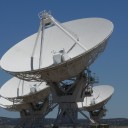
the idea to build this feed was triggered by Peter, DB2OS in January 20, when he sent me some papers and calculations from Karl, DJ4ZC, to construct a QO-100 feed with 3 helix antennas around the LNB. Additional information came from Achim, DH2VA and Michael, DD5ER, who sent me dimensions for the antenne coupler and Mario who did final adjustments on the Amsat Helix antennas in Bochum.
Building a feed with three helix antennas is a complex project, so it took three month, until April 20, to get the first feed up and running.
The goal was to get best reception and not to shade the LNB, and to get the same good TX performance of a single helix feed.
To measure the shading of the LNB I built the reflector and LNB only, without helix, measured the transponder noise and DATV-MER and then glued three dummy helix on the reflector and repeated the measurement.
this is the reflector + LNB, with three dummy helix.
Resulting transponder noise: a single helix costs about 1.5 - 2 dB. The three helix antennas cost only 0.5 dB. Also MER was about 1dB better.
My first idea to simply paralleling three helix antennas was impossible, because I never measured the 140 ohms as stated in Wikipedia or Rothammel. Therefore I tuned each helix to 50 ohms and built an antenna coupler.
2.4 GHz coupler made from brass pipes, inner diameter 20mm.
Today the new 3-helix feed went into operation. It give the same good TX performance as my single helix feed, and the good RX signal of an unshaded patch feed. The only downside is that it's a lot of work, and a good workshop is needed to build all the components.
the 3-helix feed in operation
50 ohms match and holder made from polypropylen
tuning at the the coupler input with all three helix antennas connected
vy 73, Kurt, DJ0ABR
Hi Luc,
I have it running on a PI4 with 2GB ram.
DL3MX has it running on a PI3 with 1GB (I didnt know that a PI3 is fast enough, but dl3mx is happy and showed me that it is working).
The complete Setup is now done in a SETUP page, no more programming is required to adapt it to the own system.
There is a new update available covering the new band plan and also has a new beacon lock.
vy 73, Kurt
@PA1PAS: the GPS reference frequency goes through an extremely slow PLL ( a couple of seconds). This is required because the GPS module output has a very precise frequency, but has a huge jitter.
The PLL is too slow to compensate a short term drift caused by a temperature change of the TCXOs.
A good enclosure helps to solve that, and additionally Robert's hint to put a piece of foam over the TCXOs also helps a lot.
All frequencies, including the LNB reference are derived from this PLL.
73, Kurt
in our local club U02 we are actively helping hams to install QO100 stations. Until now we have build 6 complete stations, for the cost of material only, of course. And did a huge number of LNB modifications.
While most people can install a dish without problems, one of the biggest issues for most Hams is the modification of LNBs or SDRs, soldering a POTY or adjusting a helix because special soldering equipment (and skills) and analysers are required.
I have modified an uncounted number of LNBs in my work shop and a couple of Plutos, but it simply takes too much time.
I think it would help a lot if somebody (i.e. Amsat) offers ready built feeds including a modified LNB, ready to use.
vy 73, Kurt, DJ0ABR
...
Ich hab das hinter mir, irgendwo im Forum hab ich auch Bilder mit Wärmebildkamera gepostet, da kommt man ins schwitzen wenn mann die Kabel anschaut ...
sehr interessant die Bilder. Während der N Stecker rechts relativ kühl ist, glüht der SMA links förmlich.
0,5dB Verlust sind schnell erreicht, das sind schon 10% der Leistung.
Bei N-Buchse im Poty muss man auf den Platz schauen, bei mir kommt sich der mit der Halterung in die Quere.
vy 73, Kurt
After having some Beer and Obstler I finished the Helix and did some comparisons in different configurations, here are the results:
TX-signal (received with a separate dish):
Poty: +25dB
Helix: +28dB
Transponder Noise:
Poty: 6.1dB
Helix: 4.3dB
DVB-S2 MER (measured with Minitiouner):
Poty: 7.8dB
Helix: 6.6dB
As expected with the TV offset dish, the TX signal of the Helix is almost 3dB stronger.
However, the helix shades the LNB by 1 or 2 dB, which is not relevant for SSB, but represents a significant attenuation for a DATV signal.
So what to do? Building a PA with 3 dB more power? Or buy a larger dish to compensate for the loss of MER? Or just living with these results the way they are. I think I'll do the latter.
vy 73, Kurt, DJ0ABR
 Display More
Hello to the group,
I plan to use the two types ( OCXO /GPS) of Amsat downconverters to listen to the NB transponder in a first step ;
for this, the LNB signal is injected in the upper left F connector and the 144 Mhz signal comes from the upper right bnc connector.
The jumpers voltage are in position 'by default' and the 4 leds on the right side of the pcb are illuminated except the 3rd one (green) which is blinking.
The output frequency selection is on 6 which corresponds to 144.550 Mhz.There is hiss but no audio.
What am i doing wrong ?
73
tnx
renauld on4kvi
Hi Renauld,
Running the Downconverter V3d with an unmodified LNB may cause an unspecified frequency shift, maybe out of band.
For the calculation of the output frequency (6 ... 144,55 MHz) the converter needs to "know" the LNB frequency, which is not the case if you don't use the clock delivered from the downconverter.
By default the downconverter operates with 24 MHz clock. Your LNB may work with a 25 MHz TCXO, so you need to jumper the downconverter to 25 MHz by putting one jumper as shown in the documentation. Then you should get a signal on 144,55 MHz, but with some shift caused by the different frequencies of your TCXO and the downconverter's clock.
If that works you should consider to modify the LNB to get a more precise output frequency.
vy 73, Kurt, DJ0ABR
Hello,
this thread:
SDR project for SDRplay (RTLsdr) for Linux
describes a WebSDR for QO-100
which works on the NB and/or WB transponder.
Today the version 2.0 was released.
It now includes a remote control for F6DZP's excellent Minitiouner software.
You can click on a signal in the spectrum or waterfall and the Minitiouner will tune to this signal.
vy 73, Kurt, DJ0ABR
Version 2.0 was released today with a lot of improvements.
* now it is a "real" websdr, supporting up to 20 users. Each user can tune and hear his own signal. More users are configurable if the computer is fast enough.
* automatic transponder noise measurement: the RX level on abt. 10489,250 and abt.10489,540 is measured (TX carriers are suppressed). Then it calculates the difference which is the transponder noise. Nice feature to compare dishes and receivers.
* prepared for the new upcoming bandplan. As soon as the new bandplan is released this websdr can be adapted within seconds.
a new feature for DATV is described in the WB forum
vy 73, Kurt, DJ0ABR
Github link as usual: https://github.com/dj0abr/QO-100_SSB-WebSDR_DATV-WebSpectrum
Hallo Oliver,
9360 stimmt, also 09360000 um genau zu sein.
Ich empfange mit Minitiouner-Express genau so wie du es beschreibst.
Vielleicht misst du mal die Spannung am WBin, ob es auch wirklich 18V sind.
Wenns dann immer noch nicht geht, schau dir die paar SMD Bauteile in der Nähe des WBout Steckers unter der Lupe an. Beim EInlöten des Steckers braucht man kräftig Hitze, vielleicht hat sich einer der Winzlinge dadurch gelöst.
Weiß übrigens jemand wie man die 9360 in der Minitiouner Software fest einstellen kann, dass man sie nicht jedes mal neu eingeben muss?
vy 73,Kurt
Danke für die vielen Infos,
das scheint also schon einiges auszumachen. Ich bin auf der Suche nach fehlendem MER der DATV Bake. 6,0 in einem 120cm Spiegel ist schon arg wenig.
Heute habe ich einen neuen, unmodifizierten Octagon Green HQ PLL reingeschraubt (nur LNB, ohne TX Antenne) und kam auf MER Werte zwischen 6,9 wenn der LNB ganz vorne oder ganz hinten geschoben war, oder 7.7 wenn er in der Mitte ist. Das ist immer noch nicht berauschend, aber immerhin. Ein Skew Winkel hatte fast gar keinen Einfluss, vielleicht ein zehntel.
In diesem Thread
schreibt dg0opk von MER 9,4 bei einem 120er Spiegel.
So langsam hab ich den Verdacht dass mein SAB Spiegel vielleicht krumm ist und keinen vernünftigen Focus hat (war auch eher billig), optimal ausgerichtet ist er jedenfalls.
vy73, Kurt
ein sehr interessantes Thema, ich hab mich schon oft gefragt wie wichtig das ist, und nie ausprobiert.
Wie wirkt sich das hin und herschieben aus, ist das drastisch, oder kaum merkbar?
vy 73, Kurt
Hallo Oliver,
das hört sich so an, als ob der Downconverter die seriellen Daten nur ausgibt wenn das Oled Display angesteckt ist. Das könnte gut sein. Die Firmware, welche die Daten auch ohne Display ausgibt, wurde erst vor kurzem freigegeben und hat es evt. nicht mehr auf die Boards geschafft. Das war allerdings die einzige Änderung, ansonsten ist dein Downconverter auf dem aktuellen Stand. Da du aber ein Oled Display hast, wird das wohl kein Problem sein.
vy 73, Kurt

[user='445']...
So, regardless of the diameter of your dish, you still need a -10 dB 90 degree opening angle for a f/D=0.6 dish --> 6 windings .. because of mathematics/goniometry ...
thanks for the answers,
where does the -10dB at 90deg come from?
Another "secret" number (at least for me ![]() ) is the turn spacing which is usually 0.25, but why 0.25?
) is the turn spacing which is usually 0.25, but why 0.25?
If I play with the turn spacing, a 4 turn helix can get the same opening angle as a 6 turn helix.
My goal is to make as few turns as possible so as not to shade the LNB.
Currently I use a poty feed, but want to try a helix, just for comparison.
vy 73, Kurt, DJ0ABR
Hallo Bert,
im Prinzip geht das auf einem schnellen Odroid (N2) oder auf dem Raspi-4.
Für WB muss dann ein SDRplay benutzt werden und für NB ein RTLsdr.
In der Software (in main() ) ist eine Abfrage für doppelten Start drin, diese muss man deaktivieren.
Für diese Anwendung würde ich den Odroid N2 empfehlen. Ein Raspi-4 wird bei der hohen Last extrem heiß werden und nur mit perfekter Kühlung funktionieren, während ein Odroid N2 kaum mehr als handwarm wird.
vy 73, Kurt
...
To illuminate a dish with a helix properly a rule of thumb is that you need one (1) winding per f/D-unit. So f/D = 0.6 needs 6 windings. With smaller f/D's less windings are needed, however, with less windings the axial ratio becomes worse.
...
a question to this older post,
this rule of thumb "1 winding per f/D unit", is this still valid?
Most people use f/D=0,6 offset dishes, but most use 3.5 windungs and some people 5 windings.
I am currently building a helix for a 150cm offset TV dish, f/D=0.6 and want to use the best number of turns.
vy 73, Kurt
solange ich meine Station eingeschaltet habe könnt ihr das Remote Display (und auch das SDR Projekt) selbst ansehen. Das Remote Display läuft an einem Amsat Downconverter V3d mit GPS Modul. Es ist ein Live-Bild, was man an der Uhrzeit sehen kann.
Der WB-Wasserfall und das Remote Display laufen auf einem Odroid XU4, und der NB-Wasserfall auf einem Odroid N2.
(beim NB Wasserfall nach dem ersten Start bitte "Spektrum: AUTO" anklicken und aktivieren)
viel Spaß, Kurt
Hallo zusammen,
wer schon einen neuen Amsat-DL Downconverter V3d bekommen hat, kann ein OLED Display aufstecken, was eine recht bequeme Überwachung ermöglicht.
Jetzt gibts noch eine weitere Option: ein Remote Display, welches in jedem beliebigen Webbrowser dargestellt werden kann.
Dazu braucht man irgendeinen Raspberry PI, auch uralte Boards die noch in der Bastelkiste liegen lassen sich dafür gut verwenden und wieder für etwas nützliches einsetzen. Und außerdem einen 3,3V Seriell/USB Wandler die es ganz billig im Internet gibt.
Man verbindet diese Teile, startet die Software und kann sich eine originale Kopie des OLED Displays auf jedem Gerät im Heimnetzwerk ansehen, Computer, Handy oder wo auch immer ein Browser drauf ist. (Ein OLED Display braucht dafür nicht installiert zu sein).
Diese Software und eine Anleitung ist in meinem Github Repository:
https://github.com/dj0abr/QO-1…-Converter-Remote-Display
das ganze ist noch neu und hat sicher diverse Bugs, funktioniert aber schon recht schön. Die Bugs beseitige ich sobald ich welche entdecke.
Pünktlich zur Verfügbarkeit des neuen Upconverters (ca. Ende Januar) werde ich das Remote Display auch für den Upconverter erweitern, der zwar kein eigenes Display hat, aber trotzdem einige nützliche Infos seriell zur Verfügung stellt.
vy 73, Kurt, DJ0ABR