

What should I look for beyond pcb ad8302
Posts by iw5bsf
-
-
hello dd0kp
Thanks for the information, arduino UNO standard if I'm not wrong? I've never used it
-
Thanks, I see in the image that you used a 2x16 line display and a swr gain stage and an ebay kit? what you use
73 Roberto -

Hi,
A AD8302 dB diff & phase is build based on a eBay ready PCB which display also SWR. A ATMEGA8 displays on a 2*16 LCD.
hello Geotge , on ebay pcb swr display based link ? I was interested in building it to make measurements on my feed
73 de iw5bsf Roberto
-
No for the tests I used low loss Gore brand cables but not suitable for outdoor use h155 I don't think it is suitable 2.4ghz
-
hello Thoma sorry uplink I meant 2.4 GHz between PA and helix a low loss cable
Roberto
-
Did I forget that the coaxial cable used 2.4 ghz?
Roberto
-
hello Thomas right observation !!!
Roberto
-
thanks Ed PA1EW I try to build it while I wait for your answer, I realized that I was inspired by your photo but using a reflector I had the propeller 125x125 and centered but slightly above the return loss of 28 db trying a second transponder with 2watt and dish offset of 80 cm the return signal s7
Roberto
-
 Display More
I want to present my design for a single-dish portable station as described below and partly shown in the pictures. For me it should meet the following requirements:
· Easily detachable construction (transport by car)
· Single offset dish 60cm, dual band feed
· Stable tripod mounting
· Comfortable adjustment of dish heading
· Compact “radio-box” to carry two full-duplex transceivers + SDR
· 12V operation (battery) possibility
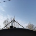
A new adapter bracket (picture 1) was constructed to mount the Triax 64 dish in a stable way to the tripod pan-tilt head. The dish's own (elevation)adjustment is fixed and not used. Another bracket (left side in picture 4) is added to carry the plastic box with Mini-GPSDO 27,841846MHz + 30MHz low-pass filter + battery pack 5V.As my modified Octagon LNB was readily available to be combined with the 5,25 turns LHCP Helix, I choose this for the moment above the patch-feed to be used as dual feed. The Helix/LNB mounting has been improved from the quick-and-dirty tape-construction to the detachable- and adjustable Helix-reflector mounting as shown in picture 2 & 3.
The construction allows also for LNB skew-adjustment rotation at any time. Releasing the two wingnuts (pictures 2 & 3) on the sides will then allow for LNB –focus adjustment, the Helix reflector is moved too. The Helix reflector is held in place also by the front-section of the Octagon LNB.
Last item to be finished is a compact housing for the FT817 (144MHz TX driver) and a TM-455E (435MHz RX). The modified MKU2424A (=B) up-converter will be placed on top. A compact 13.8VDC/22A SMPS supplies the power when 230VAC is available, when not, a 12V gel-battery could be used. Hook-up for SDRplay RSP2 is also foreseen. Hope to work you soon via QO-100 with this portable station!.
I am curious who has similar- or totally different portable constructions, please let us know and show.
73 Ed PA1EW/P
Hi, what size did you make the reflector in mm? and relative distances
73 of iw5bsf Roberto
-
sorry all post me I correct 0,5 A IR , hello db8tf excuse me model model of the daiwa
Roberto
-
 Display More
Just finished modifying another UMTS PA (BLF8G22LS-160BV) this time for OM DM4DS Sandor.
Max power easy over 100W but as my power attenuator gets very hot i stopped @ 100W (320mW drive).
Signal looks clean on spectrum analyzer.
I attached some pictures from the testbench and the used equipment.
73s DB8TF
Hi great, I see you use the Daiwa power meter but the power returned 2.4ghz?
Roberto
-
Ok, I solved PA now works at 13 watts and 0.5 mA, as a driver for tests of use of Chinese Tiquin 27 dbm out ebay but personally I don't li
73 Roberto
-
hello om0aao,
I did some tests in PA and the draiver seems to resonate a lot due to the length of the connection cable that probably resonates and influences the power supplied
Roberto
-
thank bg0aub
-
thank BG0AUB , I made some improvements by obtaining with input 0.5 at the output 2 watts bias 3v and with 3.7v bias 9watt
vcc 27v
73 Roberto
-
For mrf21045, my bias voltage is 2.7-3.0, 0.55-0.9a at 24v, and 42DB is output when 30DB is input
thank you all, sorry, but the 500 mA current must be measured on the Vg? bias MRF2104
-
Andrew MRF21045 helps what value should the polarization voltage have? I got about 3v 1 watts 0.6a or so with 3.3v 0.8a 2.5 watts if I increase the bias voltage 3.4v starts consume rest
-
Thanks, you get more output than you think is possible
-
hello the lines were not 50 of entrances and exits using copper I managed to obtain with +4 db input in out 1 watt 2.4 ghz with 20 v of power supply
Roberto