Posts by David G0MRF

    Hi George.
    The TXC standard product is a TCXO. I believe that pin 1 is used for the voltage control input......if you purchase the VCTXO option from the factory.
    So.....if it is a VCTCXO....then pin 1 will be the input.

    If it is a TCXO then pin 1 is not connected.

    73 David

    DJ7TH Glad to know your D75 is working fine. After this experience I think if I needed a 25MHz TCXO it would be worth looking at the TXC 7N series. Although I haven't tried them, there are some notes on the forum suggesting they work very well (280ppb). They are available from Mouser, who have a distribution centre in Europe.

    DJ0MY The D75 data sheet recommends 3.3V. I suspect any variation from this is likely to give a small offset in frequency rather than random drift.

    73 David G0MRF

    @PA3YFM A good question Remco. I am 95% sure it is a traditional crystal design rather than an NCO. (it even has SMD capacitors around the edge of the board) I was pointed towards it after trying the Fox series which have unusable digital steps as they compensate. A friend at High Sierra Microwave did the research and spoke to CW. He was looking for an analogue TCXO which had
    low phase noise for use in a 5.8GHz system. I wondered if there had been a change in technology between my original purchase in 2017 and the batch this year....but as the replacements work perfectly, that does not seem to be the case.

    Unfortunately, it is likely that while the current stock at the factory is OK, the distibutors may all have faulty oscillators.

    G0MJW Interesting......... I can't tell if that is 4 weeks after my duff batch...or 4 years. Time to look at the data sheet. Do I see that as 25MHz rather than 27MHz ?
    That suggests that it's not a crystal issue, but something amiss with the ADC or the feedback loop used for the compensation. Amazing that this looks to be a parameter that is not tested. The comment from CW was


    "we were quite surprised. We are still investigating the cause at the crystal level,"


    Thanks


    David

    Hello Heiner / Mike.

    The date code and markings on my batch from Digikey in January this year are:


    N71 RK5H The production lettering says 1713 So probably week 17 of 2013 (old stock?)

    My replacements are marked 2619, so it does look like MMYY in the date code.


    I am also aware that Michael DG0OPK has found similar problems with some marked
    N71 RK6L and 1713. This looks like a similar production lot.

    G0MJW I think if you have constant temperature and you can see 'hunting' then that is a product with a problem.

    To be fair, the first plot was one of the worst I had, however, even a 'good one' was showing 300 - 400Hz for no apparent reason.

    The batch marked 2619 however are an order of magnitude better and do not have any form of hunting that is visible in the bandwidths I've used. - Only long term drift with temp can be seen.....and that is better than the spec.


    David

    It appears that Connor-Winfield have been experiencing some production issues with their D75 series TCXOs. A couple of years ago I used a 27MHz unit to replace the crystal in an Octagon OTLSO and the performance when compared to the standard crystal was transformed. Earlier this year I bought a batch of the same TCXOs from Digikey. On this occasion I was disappointed to find that several of the units had very poor short term stability.

    The problem appeared to be a control loop issue where, at near constant temperature, the output would ‘hunt,’ moving up and down over a period of a few minutes. Technically, the TCXOs were still well within their 500ppb tolerance and so returning them as ‘out of specification’ to Digikey was questionable.

    Fortunately, the Conner-Winfield TCXOs are a premium product and I contacted technical support at their HQ. After sending a lengthy description, a few graphs and returning a few unusable TCXOs they performed a failure analysis, acknowledged the fault and a couple of weeks later replaced the entire batch with some straight off the production line. – date code 2619


    As a test, you can assess your TCXO in about 10 minutes by looking at the CW beacon on QO-100.

    If you use an SDR on 739MHz, set up the system and let it all ‘warm up’. This is important as there is a TCXO in the LNB but another in the SDR which will also contribute to drift.


    1) Set the demodulator window to about 2kHz as a visual reference and the bandwidth across the screen to about 10 – 20kHz.

    2) Slow the waterfall down so it takes about 10 minutes to fill the available space. Add time markers to the plot if you can.


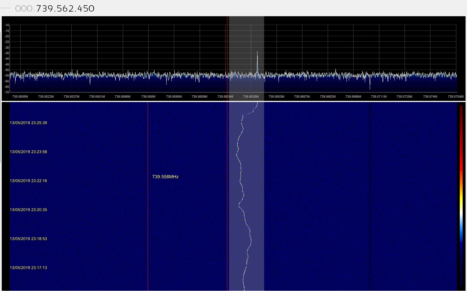
    Below I have shown 2 plots for comparison. The first is the plot from a faulty TCXO which over 10 minutes moves around its ideal frequency apparently unhappy to 
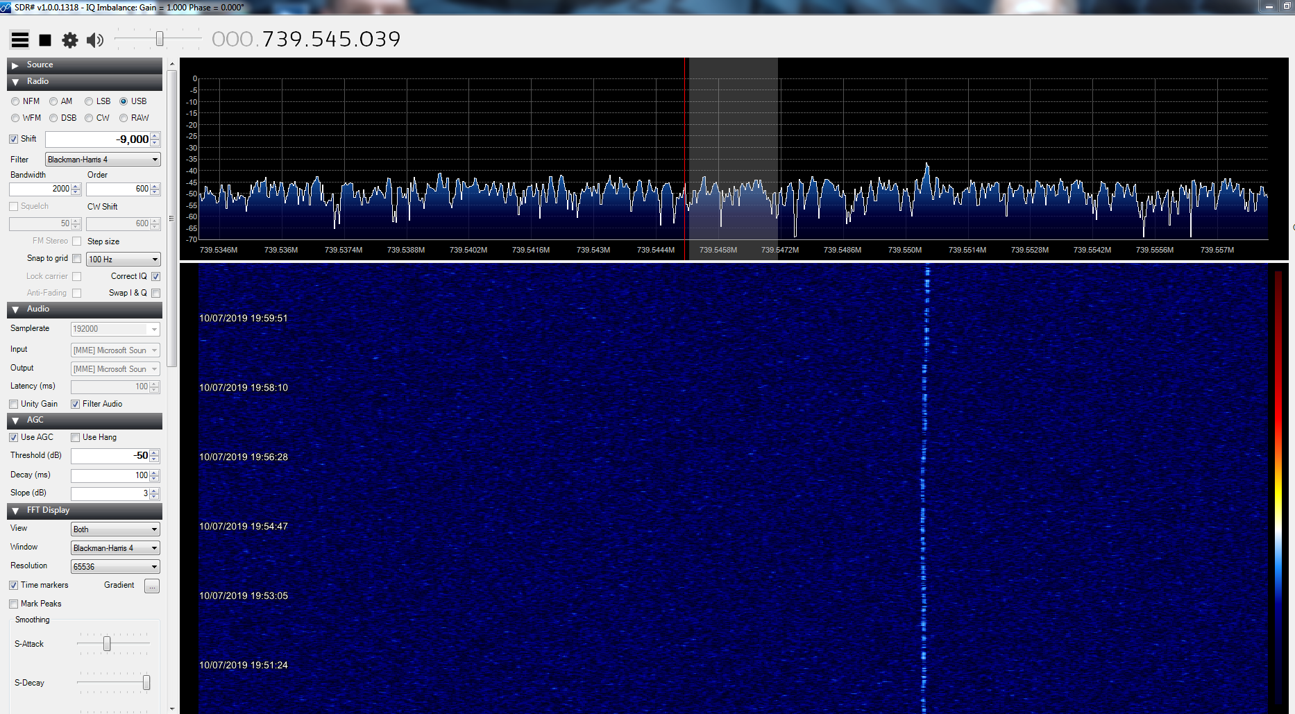
stabilise. The second plot shows the performance of a normal TCXO. In both cases a small amount of this drift will be due to the SDR’s oscillator at 739, but the majority of the drift will be from the 9750MHz VCO in the LNB.


    Thanks


    David G0MRF


    Hi.

    Things are progressing slowly with my homebrew upconverter.
    I'm about to programme the ADF4351 for a frequency of 1967.5MHz.
    The Analog Devices software has generated some info for the 6 registers but there are many 'options'.

    Does anyone know if the following settings look reasonable? Just trying to avoid a local oscillator with poor performance.


    Thanks David

    Hi Geert / Heiner.
    That conversion has been tested by BATC on my prototype.
    It works OK, but 2 comments were made.
    1) There are small losses from the PIN diode protecting the output (apx 1pF to gnd)
    2) The attenuator I used to reduce the excess gain from an LNB for a NB signal reduces the performance for a wideband DATV signal.
    If the diode is removed and the atenuator reduced, then the converter can be used to down convert 739 to 144 for the NB transponder. Or, to upconvert the WB transponder to 1336MHZ.

    73 (and tnx QSO Heiner)

    David

    Hi Georg.

    The Pluto needs a little bandpass filtering in addition to a PA.
    If you look at the RFPA5208 from Mouser, that has enough power to drive a larger PA and 40dB of gain. So, a possible solution would be .....Pluto / SF2124E Band pass filter / Resistive pad as required to set output level / RFPA5208 / optional Low pass filter.
    You will get up to 600mW to drive a PA.
    That can drive the commonly used Chinese Wifi amp to 3W (advertised as 8W) without problems. apx 170mW drive needed for 3W out.
    See you on QO-100

    Thank you for the links to Arduino code. I also found some examples of PIC code on the BATC site, so now I have a choice. Just one frequency 1967.50 MHz required. Will take a closer look over this weekend. :)
    73 David

    Looking at the original photo #1 on this thread, it looks like there is a lot going on between the output of the device and the SMA connector. On the data sheet it suggests that at 2.4G there should be only a 1.5pF capacitor to ground. Personally I would disconnect all those components and just AC couple the output to the SMA.
    Here I've just received some Qorvo RFPA5208 ICs from Mouser. Now I need to design the board for the rest of a low cost upconverter.
    The RF should be fine....but setting the frequency of the ADF4351 with a PIC sounds like hours of frustration. Can a PICStart+ program a 12F629 ??

    Hi.

    I can confirm that shorting pins 4+5 together as detailed by George Smart works very well. The amplifier is in TX mode all the time and even though the TX quiescent current is 'always on' it does not cause overheating. - Nice mod. Thank you George.

    What would be nice, is if there is some work on improving the matching at 2400. At the QO100 frequency gain is 13dB. Claimed gain in the middle of the Wifi band is 17dB. Would be nice to find another couple of dB and reduce the input drive a little.


    73 David

    'Stability' is a bit of a moving target and means different things to different people. The software solution or an external GPS locked source fed down the cable to the LNB are at the top of the list on performance. However, it's worth remembering that we are nearly all used to tracking doppler, so a bit of drift is not going to be a disaster. The reality is surely that over the time of a QSO we do not have to retune. For SSB that could mean 100Hz in 20mins is acceptable. But for JT-9 you would need better than 3Hz in 1 minute. So perhaps look at what you need in terms of performance and then decide how to get there. - See you on P4A !!

    There is a PCB for my design available from Luciano PT9KK, an AMSAT member in Brazil. (See post above....Hi Luciano ! )

    It Uses a Si590 oscillator module on 595MHz from Digikey.

    Includes a bias Tee for feeding the LNB and 2 outputs, one attenuated at 739 and one at 144MHz for the narrow band transponder.

    David G0MRF