Posts by G8UGD

    I have tried a UDP stream via from OBS and even OBS > ffmpeg and it seemed to last for around 30 seconds with minimal delay, but then stops, so I thought there may be checking for the H264/H265 box? My reasoning was I got something like a 9 second latency with the rtmp stream and 4.5 seconds udp. Then I changed a few of the settings in OBS and got rtmp down to 5 seconds which will do me for the time being. I think there are many variables outside of the Pluto to consider. It is not easy for me but I am trying to understand the scripts within Pluto to gain better understanding.


    Adrian

    Ich habe vergessen zu fragen, ob Sie Windows oder Linux für OBS verwenden, da Windows anscheinend nur ein Minimum von 64 Kbit / s für Audio zulässt, wobei Linux auf 32 Kbit / s Audio herunterfällt. Stellen Sie sicher, dass alle Audiospuren auf Minimum eingestellt sind.

    Es ist ein Ausgangspunkt für mich, und ich arbeite daran und beginne, Dinge wie Auflösung usw. voranzutreiben. Hinweis: Ich arbeite auch nur mit einer Bildrate von 15 Bildern pro Sekunde.


    I forgot to ask if you were using Windows or Linux for OBS, as windows seems to only allow a minimum of 64Kbps for audio, where Linux will drop down to 32Kbps audio in each case make sure that all the audio tracks are set to minimum.

    It's a starting point for me and I work from these and start to push things such as resolutiion etc. Note I am also just running at a frame rate of 15FPS.


    Hallo Manfred;

    Ich fange an, ein sehr ähnliches System zu verwenden, abgesehen von einem FEC von 3/5 und wahrscheinlich einem langsameren PC, bei dem es sich um einen Core-2 Quad-Prozessor mit 3 GHz handelt

    Ich habe Screenshots meiner Einrichtung gemacht, damit Sie diese für 333KS ausprobieren können. Ich hoffe, es hilft.

    Ändern Sie Ihre IP in Ihre eigene IP, wenn über den USB-Port wahrscheinlich 192.168.2.1.

    Dies basiert auf QPSK bei 333 3 / 5FEC mit einer TS Net-Bitrate von 396 kbit / s.

    Ich hoffe, es hilft.

    Adrian


    Hello Manfred;

    I am starting to use a very similar system, in fact apart from having a FEC of 3/5 and probably a slower PC, which is Core-2 Quad processor at 3GHz

    I have taken screen shots of my set-up so you can have a go with these for 333KS. I hope it helps.

    Change your IP to your own IP, if through the USB port probably 192.168.2.1.

    This is based on QPSK at 333 3/5FEC which has a TS Net bitrate of 396.kbps.

    I hope it helps.

    Adrian

    I must admit to preferring some slightly bigger units, but not for receiver side I am not that clever to design boards.


    I built two of these style ID filters for transmit, one is directly out of the SDR unit and another after the pre-drivers just before the main PA, the idea is to reduce any spurs from the SDR or spurs from the pre-driver stages up to about 2 watts.


    On the trace I had approx 0.3/0.4 dB insertion loss and the divisions were 50 MHz per division horizontal and 10dB per division vertical.


    Adrian

    Hello Manfred thanks for the response and I did see a nice signal from you on the Sat.


    10:59 G8UGD Adrian DK5FA a nice MER of 7.1 D4 on a 1.05m dish


    500KS is an odd thing as it is not mentioned in the band plan at all, it goes 2MS, 1MS, 333KS, 250KS and then 125KS, then again neither are the others 66KS 50 KS and 33KS.


    Software like MiniTioune Keeps 500KS on receive below 10,497 MHz, but many will consider 500KS as Narrow band as it is not 2MS, and I believe considered Reduced bandwidth when used on 146MHz Operation.


    Wish all the best for the New year to you and your family.


    Adrian

    DK5FA

    Hallo Manfred; Ich hoffe, es macht dir nichts aus, wenn ich frage, was blöde Fragen sein können. Was haben Sie in Bezug auf die Leistung einiger der Übertragungen als bedenklich empfunden, da ich der Meinung bin, dass Google Translate keine sehr gute Arbeit geleistet hat, der ich folgen sollte? War es nur die Bandbreitenübertragung oder eine über 500KS Abtastrate, die höher war als das Beacon? Oder waren es weite Übertragungen im reduzierten Bandbreitenbereich?

    Ich denke, es gibt viel Verwirrung bei den Leistungsstufen.

    Übertragungsleistung
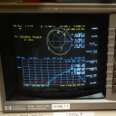
    Alle Uplink-Übertragungen sollten möglichst wenig Strom verbrauchen. Keine Übertragung sollte ein Downlink-Signal mit einer höheren Leistungsdichte als der Beacon haben - der webbasierte Spektrum-Monitor ermöglicht es Benutzern, ihre Uplink-Leistung einzustellen, um dies zu erreichen.

    Aber im nächsten Abschnitt heißt es:
    Benutzer sollten mit DVB-S2-Modi höherer Ordnung mit niedrigeren Symbolraten experimentieren (z. B. 333 KS 32APSK), um Bandbreite für andere Benutzer zu sparen. Dies würde viel höhere MER's als das der Bake erfordern.

    Ich glaube, der zu beachtende Ausdruck ist "Leistungsdichte", in meiner vereinfachten Denkweise "Leistung x Bandbreite". Also nochmal mit einer sehr vereinfachten Ansicht. Wenn Sie mit einer angezeigten Leistung von 8 dB über 2,7 MHz Bandbreite bei einer 2000-SR-Rate von 21,6 dBMHz senden. Also also ein 333-Signal; welche bandbreite von 0,45 mhz kann ein angezeigtes db von 21,6 / 0,450 = 48db haben und hat dann die gleiche leistungsdichte wie das 2ms signal? Dies würde natürlich auch für 32APSK nie benötigt werden.
    Ich kann mich natürlich in der Interpretation irren, würde mich aber freuen, den richtigen Satz zu finden?

    Der Wortlaut dessen, was übertragen werden kann, würde jedes Video über 10 Minuten hinweg entfernen, es sei denn, es ist AMSAT-Geschäft und würde uns grundsätzlich zu Video-QSOs und Video-Streams unserer eigenen Stationen führen. Ich habe einmal die Verwendung von Cartoons und Holiday-Werbevideos in Frage gestellt, da ich dachte, dass es sich um Werbematerial handelt, aber mir wurde gesagt, dass es sich um hochwertige Quellen handelt, die zum Testen verwendet werden!

    Ich gebe zu, dass ich es genieße, Landschaften aus der ganzen Welt zu sehen, da es für mich von Interesse ist, Orte zu sehen, an denen ich noch nicht war und die ein oder andere Video mit Szenen aus dem Vereinigten Königreich gesendet habe, und ich wäre enttäuscht, wenn das nur als klassifiziert werden könnte allgemeines Interesse für andere Amateure sollte als zu beanstanden angesehen werden.

    Ich mag die Amsat.dl-Site für Themen wie diese, da das BATC-Forum nur technisch zu sein scheint.

    Alle Google Übersetzer entschuldigen.

    Grüße

    Adrian


    Hello Manfred; I hope you do not mind me asking what may be stupid questions. What did you find objectionable with regards the power of some of the transmissions, as I do not think Google translate did a very good job for me to follow. Was it all bandwidth transmissions or ones over 500KS sample rate that was higher then the beacon? Or was it wide transmissions in the reduced bandwidth section?

    I think there is a lot of confusion on power levels.

    Transmission Power
    All uplink transmissions should use the minimum power possible. No transmissions should have a downlink signal with a higher power density than the Beacon – the web-based spectrum monitor will enable users to set their uplink power to achieve this.

    But it goes on in the next section to say:-
    Users are encouraged to experiment with higher-order DVB-S2 modes at lower symbol rates (for example 333 KS 32APSK) to conserve bandwidth for other users. This would need greatly higher MER's then that of the beacon.

    I believe, the phrase to note is 'power density', in my simplified way of thinking 'power x bandwidth'. So, again with a very simplified view. If you are transmitting with an indicated displayed power of 8dB over 2.7 Mhz bandwidth for a 2000SR rate = 21.6dBMHz. So therefore a 333 signal; which has a bandwidth of 0.45MHz can have a displayed dB of 21.6/0.450 = 48dB and will then have the same power density as the 2MS signal? This would never be needed obviously even for 32APSK.
    I may be wrong on the interpretation of course, but would be happy to discover the correct phrase?

    The wording of what can be transmitted would remove any video over 10 minutes unless it is AMSAT business and would basicically lead us to video QSO's and video streams of our own stations. I did question at one time the use of cartoons and Holiday promotional videos as I thought they would be copywright material, but was told they are high quality sources used for testing!

    I will admit that I enjoy watching sceanery from around the world as it is of interest to me to see places I have not visted and have sent the odd video of scenary from around the UK and I would be discuranged if what may be only classed as general interest to others amateurs should be considered as objectionable.

    Just some of my ramblings, I like the Amsat.dl site for topics like these as the BATC forum seems to be technical only.

    All Google translate sorry.

    Regards

    Adrian

    Hello Peter;

    Nice to know, thank you.


    I was just wondering if there will also be a revamped band plan at some point, such as the 1 MS slots moving down to fill the space and more RB slots at the top? I am sure it is already in hand and well thought out.


    Adrian

    Personally I am using the POTY, but I know of two that have just bought what I believe is the DJ7GP design from Passion-Radio, they are not in use yet, but they do have a tuning screw that has not been tweaked by them!

    So I am hoping for them it to be OK. I did not realise there was two versions of the antenna before I saw this post and I was trying to determine the physical difference between the two to check.


    Adrian

    Yesterday I made some not so scientific measurements. I compared Bamatech DJ7GP and PE1CKK POTY 2.4GHz patch antennas. Already known that DJ7GP design is not circular polarized but POTY should be.

    Can I ask why you say the Bamatech is not circular polarized the web text says it is, I am curious as I know a few that have just bought a couple of these????


    Adrian

    Microwaves are uncharted waters to me, esp when it comes to amplifiers like this.

    I am very new to this as well, I just spend lots of time in this stupid computer, playing catch up now I have time on my hands. If you have the mod sheet for the amplifier then the sites I read up, are mentioned in the mod pages. The first one I saw done with James Smith when he also posted on Facebook about it and G4WIM also did his before I did mine. My aim was to keep everything under the screening lid hence the reason behind my mods and going through the bias circuit. I would love to have a way to program the variable electronic potentiometer IC on the board that is doing the biasing, but I do not understand enough of that yet.


    Have fun.


    Adrian

    Mike if I can find your email I will send you the mod sheet that I initially followed for the mods and other than that, the biasing is up to you. I have other pictures from other peoples mods as well, but would need to zip up and send.


    Adrian


    Must get back on the air first.

    Hello Toni;

    I will try to answer the best I can in my own words on why I think it is better, I can not prove it or disprove it. The modification information from SP8XXN and SP5XMU mention the board is a Doherty amplifier. In reading up on these amps (wiki style) one device is switched on in class AB and the other is basically class C and off, needing a high peak level to switch it on, as it is used for the high peak to average transmissions of UMTS.


    The article I read also said that power is lost as the input power is split two ways into each device by a 90 degree phase shift with different lengths of track, so in my mind half the input power is being diverted to a device that will not amplify any signal until it reaches it's designed peak switch on point. I have no idea at what level this is!


    So to me, to get back this wasted input drive the second device needs to be biased as the first, in a class AB mode.


    Now as it was designed for around 2100 MHz the 90 degree phase shift is not going to be 90 at 2400Mhz as the tracks are longer then required, but any phase shift change on the input is being reversed on the output or close to it.


    As to drive level, I know that my pre-driver starts to limits out at less than 2 Watts, I have also reports that others that have done the mods have achieved a very maximum of 120 plus watts for short periods and this is NOT something I would recommend, I have taken mine to an excess of 90 watts before my nerve gave out.


    There are others doing similar mods, in fact a James Smith posted on facebook and in in IO groups

    https://groups.io/g/DATVPA/top…_amplifier_using/34475663?


    James is probably the first that brought it to my attention followed by a local radio ham Tim G4WIM

    PA für 2,4 GHz


    Each has done it a slightly different way but end up with similar results. I have been to Tim's location and know his test gear is accurate. Do try and have a look at both links.


    Do not expect to run the devices at full power and for them to last long also. Do not forget you need something like a peak to average difference of 6dB, but if you know that the peak output is say 80 watts that is 3dB better than saying the peak output is 40 watts and the average is 20 watts rather than 10 watts.


    I hope this explains it from my perspective, it is probably the best I am capable of giving. :)


    Adrian

    OK thanks

    I was looking for something to help a couple of new starters get correct alignment of the dish/dual feed etc. Mintiuner needs time to lock and provide an MER as does my GT-Media sat finder, so something that could see all 8 plus MHz of the band and not rely on high processing power when pushing an SDR over the range. Something will crop up to mind at some point. Thanks for the heads up on future development.


    Adrian

    I should have been more descriptive, looking for a scan style app that uses the tuner of the Minitiouner and displays signals it receives, similar to a spectrum analyzer.

    The QO100_Live_Tune is taking the BATC WB server and using that as an aid to set freq and SR rate on the Minitiouner, is relies on a internet connection. That is a good app for fast tuning and works well, but not what I am after at the moment.

    I have modified the two amp's I have, I have removed the input circulator and the input 2.2Ghz filter but left the output circulator in place, I am glad I did as I burnt out the cheap Ebay 50 watt dummy load at some point and did not realise. So the circulator would have been taking all the load in effect.


    Going off my circuit above I have done a few mods in changing the 1K1 resistor to a 1K0, removing the 250 Ohm to ground and adding another 4K7 to ground all on the right hand side of the board. I have also cut the track feeding the emitter follower and fed in to another point. The end effect is that both devices now have the same bias voltage.


    You may just notice where I cut the track under the end of the white wire!

    Is it the best way of doing it, probably not, it is probably better individually biasing each device for a set standing current that way you know each device is taking the same current. Out put powers have been in excess of 80 watts. The other mods have been snow-flaking, cutting tracks and removing an input cap as per some posted mods. Do be careful, the more you push these the more prone they can be to self destruct.

    OK, went a different route to 'import sys' as I found a tutorial on another method which is probably a lot safer.


    I am up to this at present:-


    #!/usr/bin/env python2
    # -*- coding: utf-8 -*-
    ##################################################
    # GNU Radio Python Flow Graph
    # Title: dvbs2
    # Generated: Sat Aug 3 00:17:48 2019
    # Modified for external command line variables G8UGD 26/11/2019
    ##################################################

    from gnuradio import blocks
    from gnuradio import dtv
    from gnuradio import eng_notation
    from gnuradio import filter
    from gnuradio import gr
    from gnuradio.eng_option import eng_option
    from gnuradio.filter import firdes
    from optparse import OptionParser
    import osmosdr
    import time
    import argparse

    parser = argparse.ArgumentParser(description='Frequency, IF gain and Symbol rate')
    parser.add_argument("-cf", default=2409.7, type=float, help="This is the 'cf' centre frequency variable")
    parser.add_argument("-ifg", default=1, type=int, help="This is the 'ifg' TX IF Gain variable")
    parser.add_argument("-ks", default=250, type=int, help="This is the 'ks' Symbol rate variable ie 250, 333 etc.")
    args = parser.parse_args()
    cf = args.cf
    ifg = args.ifg
    ks = args.ks


    class dvbs2(gr.top_block):

    def __init__(self):
    gr.top_block.__init__(self, "dvbs2")

    ##################################################
    # Variables
    ##################################################
    self.symbol_rate = symbol_rate = ks * 1e3
    self.taps = taps = 80
    self.samp_rate = samp_rate = symbol_rate * 2
    self.rolloff = rolloff = 0.35
    self.resample = resample = int(round(5e6/symbol_rate))
    self.center_freq = center_freq = cf * 1e6
    ##################################################
    # Blocks
    etc


    I have never programmed in Python so I am sure there are better ways at doing this, Changing the modulation and FEC seem to be more difficult, but I will continue to try. It keeps the mushy grey matter healthier.


    Adrian