Posts by G8UGD

    Have have completed most of the mechanical mounting, done mine side by side as per the cover.

    Dry run up to now no heat-sink compound. I still have to modify the boards, sort out cables, get a 28 Volt power supply, and find an overall enclosure. So still a fair time off completion yet. I plan to drive one of the units with my small MHL 21336 amp, not sure if it will be enough so will just have to wait and see.


    As no one else has replied I will have a guess it is down to the level of noise power that the input has to deal with the wider the more noise the narrower the less noise, well I am probably thinking of analogue receivers but I can not believe that SDR would be any better.

    When you are reducing the sample rate you are reducing the bandwidth the A to D converter deals with.


    Have a read of this:-

    https://www.electronics-notes.…ratio-s-n-snr-formula.php


    Adrian


    Before I forget and you reduce the sample rate to 250 KHz and leave it there you may notice that signals can disappearoff one end and wrap around come back in view as though traversing in the wrong direction or come back in at the other end of the view screen. I believe that can be down to something called aliasing. Some thing I barley understand as I am still old school, but have come across it several times when playing, something about sampling at at east twice the rate of bandwidth you wish to see.


    I am sure there will be more brainier people along soon.

    DF1QE Good morning and thank-you, you are of course correct. I made the assumption it was a 4 pin TXCO as the bottom left pin is at ground and it matched a data sheet. Checking this morning with power applied there there is no VCC to the chip, so I bow to your better understanding of these LNB's. If it is a typical inverter input stage on the chip anyone know which is input and which is output or is it a case of play and see? All the images I have seen do not seem to be the same 3556E.


    A new day starts.


    Adrian

    Hi Dave I thought for a second you were pointing me to a 3566E spec sheet. I hope to use a OCXO I have for the job, and put it all out side in a box at some time as I slowly improve the set-up, receiving SR33K and SR66K video can be fun when the LNB can drift more then that. But it also should add some stability to RX for narrow band as well. Thanks for the link.

    I have been using a cheap TRIAX single LNB to date, it's got a PLL oscillator but can still drift quite a lot.


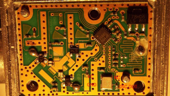
    As I had a spare I thought I would have a look inside. The unit seems to use a small surface mount TXCO of some description, the only way I could see some of the details is by taking a picture.


    As it uses one of these oscillator blocks, I think it could be easy to modify by bringing a small cable through the lid!


    I read a few conversions from crystals to external and discussions about driving single or double ended etc.


    I think I have marked the osc correctly, does anyone have a data sheet on the 3566E

    It may not be the best idea but something I think I will have a play with.


    Adrian

    Still there now although somewhat reduced, there is still a small carrier at 10,489,738.850. There was some large humps in the noise floor a few hours ago.


    Not sure if caused by the OP's transponder or not. It may be an interesting concept, but doing so over the satellite is not something I would have thought should be tried out on air. I thought requests had to be submitted to run repeaters and this is basically what it is? There is potential for interference to users on the satellite from others signals in the OP's vicinity. I wonder what the people at Goonhilly, Amsat and Qatar think about it?

    Watch out these boards are fragile and bend easy around the circulator hole. ;( Do not drop one!


    I have done my MDF modelling and got it to a stage where I think I can mill the base plate.


    I have been surprised at the cost of aluminium, planning on mounting them to a 6.35 mm thick aluminium plate and then bolting that down to a heat sink rather than drill and tap into a heat-sink and hit fins. The holes in the cover piece are not symmetrical and that threw me for a while.


    Going for two mounted at the same time, not to have both powered up but one as a back-up and have a larger heat-sink area. Also should be able to have fan cooling. This will be a longish project I should think.


    Adrian

    I was working on a dxf file with all the drill points and pockets for the PA transistors and the circulator yesterday. I measured the PA drop to be 0.7mm and the Circulator drop at 1.59mm. If you are going to remove the circulator then I think the brass shim will work OK the difference is only around 7 or 8 thou. I am lucky in that I have a milling machine with home brew CNC. Before I use it in earnest I intend to try it on some mdf to make sure the holes are correct as measured. I am thinking of 4mm screws for the cover and possibly 2.5mm screws for the board as I could not get a 3mm drill shank through the board holes.


    Once I find it is all OK, I will post the dxf on here just in case it helps others.


    Adrian

    DD0KP Heiner,

    My boards have just arrived and looking to see how I would mount them on a heat sink. I notice that the board is not flat with the bottom of the heat-sinks on the PA devices, there is a slight gap between the two surfaces.

    To make them fit on a heat sink have you milled out pockets for the PA devices and removed the circulator?

    Are you being serious?

    This came with my BU500 and I have been active on the band for less than 2 weeks, so a new unit.


    It is not just the LO that may need to be attenuated but images of the mixing process. One can not just rely on the antenna to filter out unwanted products being radiated.

    As far as I can tell the LO is not switched but always running, I have seen no mention of this function in my user documentation and I have a new unit?


    But yes the instructions do mention using a notch and BPF in all examples and the lower the input frequency then the tighter the BPF will need to be.