

I suspect the noisyness and instability of the DRO would not help your efforts as I'd expect the signals to be "smeared out". I'd suggest to get a PLL LNB still. If you webshop, order two or three, so you can have an "accident" with one should you decide to GPS-lock your LNB in the future.
Posts by pe1hzg
-
-
Hi,
The lower beacon (10489.500) beacon is FSK (much appreciated!) but the top beacon, at least on the Goonhilly SDR, has an additional carrier. Is this intended? Why?
-
Since we're now using the skirts of the transponder filter, sensitivity varies and with that the operational instructions on uplink power become more confusing.
I'm using the Goonhilly WebSDR, assuming that it's calibration has been looked at.
In the old days, there already was a difference between the PSK beacon (-69 dB) and the CW beacon (-72 dB)
In the new situation, the PSK beacon is still -69dB, but the lower CW beacon is now at -76 dB, the upper CW beacon has a similar level (but I'm not sure, since the space carrier doesn't seem to switch off)
In any case, this now gives 7dB of ambiguity as to the max uplink level ("not stronger than the beacon"). Comments?
-
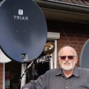
One thing to consider is that by adding a reference frequency input via the coax, we make the voltage of the coax available via a series resonant circuit. So, any alien voltage (think ESD voltage) now finds it's way to the sensitive ports of the oscillator of the LNB chip.
The standard F connector connects inner pin first before ground connection is made. This is like the audio tulip plug; the hum of connecting an audio source to an amplifier via tulip has blown many speakers.
With the F connector, the inner pin can launch ESD voltage to the inner oscillator before ground is made.In my LNB's, I have modifications to make them run on low-noise 5V (for the PE1CMO kit) and to avoid connecting 13/18V to the 5V input I permanently added an F->BNC converter, tied ans secured through heat schrink tube. This has the advantage that on connect, the connection is made to ground first, so I don't have the ESD issue.
Perhaps something to ponder,
Geert Jan
-
A question: asked before but unanswered: why do satellites like this use LO's with this accuracy?
Is there a technical reason for this?
-
Related.. I wonder why the transponders in these sats (not ours, the regular transponders) need to have such a high stability?
After all, regular TV transponders are 8MHz "bent pipe" frequency translators.
For analog CATV on modern, I know that all the carriers of all the analog TV signals were phase-locked, the reason being that the intermodulation product of the carriers of these AM signals would then be a DC signal, and hence not visible, so CATV operators were able to push more channels on the bandwidth.
I'm not sure the same argument applies for sat-TV: on CATV, the signals all have the same strength and there is quite some amplification / processing in the network. On sat-TV, signals are spread by direction and polarization so I'd expect intermodulation to be less of an issue.
Yet, sat operators use these ultra-stable frequency references. What am I missing?
-
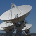
But this tower not exclusively for QO-100, I suppose.
For QO-100 just a small tripod with 60cm dish would be sufficient.
The tower pictures are from previous year. But I agree, I won't use the tower for QO100 use.
For one, because a tower like this is always moving a bit because of wind and temperature changes, which will play havoc with the small opening angle of the dish (new PA3FYM QO100 term: "tower QSB").
Secondly, because adding a large dish at height will seriously add to the wind load of the mast, which will be substantial because the dish will need to peek over the row of treesThirdly, because adjusting the dish at height is awkward and frankly I rather let the builders deal with the climbing procedure (*not* trivial - everybody has double security!)
The tower will sport HF dipoles and quad antennas, 2m (beam and vertical), 70cm, 23cm, and ATV on 23 and 13 cm.
I think we'll be around .740 as a frequency suggested earlier by Remco. Note that it is likely you will find another operator: there are several licensed scouts in our group and as none of them have used QO100, I'd like to given them the opportunity to experience the bird.
-
Thanks for the detailed explanation.
You subtract the transmitter instability from the receiver instability. I agree that would be true if I were to listen to my own signals. But, if I were to listen to your signal, would the total drift not be the addition of the drift of your transmission equipment added to the drift of my receiver equipment? .
-

pe1hzg How high is the tower?
In final configuration, 44m, measured by the remaining length of the coax cable on the ground. At the time the picture was taken, the middle tower was still being constructed. Once constructed, the centre pole gets the antennas and rotor installed, then hoisted up, so the final config is higher than shown in the picture.
Construction starts tonight, will complete on Friday morning, dismantling starts Sunday afternoon and tower is completely dismantled Sunday night; we are in the city and need to consider vandalism so we cannot leave stuff "out".
I feel privileged to be able to support this group. Call us via PA1PTP/J!
-

sbout jota in the coming days what frequency should you use QO-100?
Is there a list of Jota stations operating on qo-100 ??
Please see this link for a discussion on the Dutch hamradio forum:
http://zendamateur.com/viewtopic.php?f=21&t=21287
From the thread I see PA6PSG/J, PA1PTP/J, PE2AAB/J, PE6SBW/J, PA3RVG/J, PE1NIL/J, PA4AGO/J, PI4ADH/J, PA6SHB/J (tree issues), so that's 9 stations already (that's 5% of the JOTA stations registered for the event in the Netherlands).
Unless the forum thinks otherwise, I was planning just to call CQ jamboree and see who answers. Note that we are also interested in non-JOTA stations, especially in foreign locations.
-
I'm not sure this is a good idea.
For reception, you now require the mixer to give an output signal on 28 MHz. The typical LNB output circuit is not designed for this; I'm not sure if the chip works correctly this low. If the chip does work, the LNB circuit certainly won't; it needs to split between DC power and IF output (normally 950-2150 MHz) and the circuit is not designed for 28 MHz - the coils printed on PCB have too low inductance. I would replace that with a parallel-resonant circuit resonant on 28.675 MHz.
(an argument can be made for the noise from the image frequency but perhaps that also applies for those who mod their LNB for 432 MHz out)
For transmit, you will find it extremely difficult to filter out the image frequency, 2371.5 - 28.55 Mhz (to use your example). You need extensive filtering, very hard to archieve. In general, try to make your IF at least 10% of the output frequencey (minimal 240 Mhz). That is why many choose 432 MHz.
Even a transverter 28 -> 432 Mhz is difficult, again because of the 10% rule.
I'm sure others can give additional suggestions but perhaps this already gives you something to consider.
-
I discovered that the combination of the 4351 board and the 12F629 circuit does not like a slow rise time supply voltage. My bench PSU had a 70% fail record where the data would not be loaded correctly into the 4351 registers at switch on.
Congrats on the colloquium, Especially with the scheduling these days it is impossible to attend (I suspect attendance from would-be JOTA people is quite low; the VERON moved the event to November for a reason). Anyway..
Looking at the source code, there is quite a bit that can be done to improve reliability: use of the brown out detection, putting a delay loop at the beginning, perhaps send a few dummy bits before clocking in the real data (so that there is no confusion because of the direction programming).
The code I wrote for the attiny85 (published elsewhere on the forum) also carefully uses delay_us(1) to let things settle and to make sure signal ordering is OK. I also use a very low clock of the mcu; the PIC code I saw uses the internal 16 MHz oscillator. I'm not interested in programming speed, I'm interested in reliable, correct initialization.
Now the dust from the colloquium had settled, perhaps worth another poke?
-

pe1hzg Jan, the reason is to give you a simple setup for both transponders. you can also receive the nb im you are listening the wb.. only 3db less signal.. nice weekend..Heiner..
The isolation between H and V is more than 3dB - in fact, in broadcasting H and V polarisation are used to distribute different signals on the same frequency.
If WB and NB would have used the same polarisation, one LNB would receive both at the same time. I'm now using dual LNB's for that reason. Not the end of the world but I wonder about the reason for this this this way on QO100.
-
Something I'm just wondering..
The narrow-band transponder uses RHCP on uplink and vertical polarisation on downlink.
The wide-band transponder also uses RHCP on uplink but uses horizontal polarisation on downlink.
Why is the downlink polarisation different?
Why is the uplink polarisation the same?
(I do see it's a lot easier to switch the polarisation of a LNB than of a circular antenna - still I wonder what the advantage is of different downlink polarisations?)
Geert Jan
-
I wonder if the plain PCB, without case, would suffer the same fate?
While I am sorry for your impounding, keep in mind that power supplies that interfere with HR receptions for miles, that may explode and catch fire, without CE markings, or with faked CE markings, are shipped to the EU by the millions. Every amateur magazine now carries stories every few months about a foxhunt to find an interfering charger / lightbulb at a neighbour that is either helpful or not helpful at all.
We can't blame a customs officer for triggering on something which (s)he incorrectly recognizes.
I do hope anfang 1/1.c will help you to get this released.
-
Given the recent turmoil on output levels, a perhaps useful suggestion:
Using the level indicator on WebSDR does not work well, you have to look at a number that jumps on the screen
I found that a by-default disabled feature on WebSDR may be useful to get a better view, the signal strength plot, in slow mode. See these graphs:
The CW beacon is at -72dB. You can easily see the difference between stations, a quiet period, and who is perhaps overdoing it a bit. Perhaps it is useful to add a red line at -72dB

Perhaps obvious, (but I had not seen it on the forum), hopefully useful,
Geert Jan
-
If this is to connect a POTY antenna - I have been fairly happy with this: link.
While I agree with Remco - "use an SMA connector" - cables with N connectors are typically fairly thick and stiff and I worry that movement and temperature may mean that an adapter will put a fair amount of strain on the SMA connector and a short and flexible cable is also strain relief.
-
I do not have a SF8008 at the moment. But I asked many people to help which photos of the components to check wish possibilities we have. Nothing until now happened.
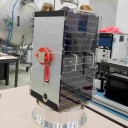
I opened it up and voided the warranty on mine, and this is what I found:
It seems this is an RDA5815. It is possible to find datasheets for it, and the specs says it goes as low as 230 MHz (!) but the datasheets i found do not include programming info.
I'm still struggling to rebuild OpenATV from source (before I can attempt to make changes) but I thought this would be of interest.
-
The WebSDR, especially the goonhilly WebSDR, is part of NB-transponder lifestyle. I wonder if the frequency trace can be clearly marked (changing colour) for a signal that is too strong? Objective, automatic.
-
Yes you do need to modify the PLL, not because of stability but because the tuner will not work below 950 MHz. Therein lies your solution to offsets.
Do we know for certain that the hardware of the SF8008 sat receiver does not tune below 950 MHz and this isn't a software limitation?
The SF8008 also runs OpenATV. I have tried (but so far: failed) to build my own image from source code - once I have that working I can see if there is a software limit that can be bypassed.
Did anyone open the tuner module? Do we know what silicon is used there, and if perhaps the silicon can be coerced to work on lower frequencies?