Posts by DK1ML

    Hi Thomas,


    I am talking about the center beacon at 10.489.750,00 as shown on the picture.


    This is the center frequency of the SDR range at 0 (zero) hertz.

    All SDR receivers have this "blind" frequency in the middle of the reception range, sometimes with a phantom signal if the balance is not accurate or if there is some 50hz hum.


    I have set the range of my online WEB SDR 5khz left of an important signal.


    But more important to me is that you confirmed the same frequency error at 10489750.08


    73, Mike

    Hi,


    after change of the bandplan the UK WEB-Sdr is -80Hz off frequency.


    By the way, it is not very smart to set the center frequency of the Sdr to the beacon frequency because of the zero point at the middle, what is shown as a black bar.


    It will be nice if somebody can inform the responsible old man :)


    73, Mike

    Hi Frank,


    I think, that a used Windows Notebook for less than 100 EUR with the SDR-Console is more powerful and cheaper than a 50 EUR Raspberry Pi with touch display that alone will cost around 100 EUR.


    That is the reason for the lack of demand for your good software,


    73, Mike

    Hi Daniel,


    a simple single wire cable from the PTT pin of the transceiver to the up-converter will be fine.


    Another option is that you use a bias tee to provide the PTT signal via the coax cable. This kind of power injector is used for the lnb power too. Just insert another one at the if-output of your rig which is connected to the PTT line.


    73, Mike

    Hi @ll,


    there are some stations with massive audio distortions using the Kuhne Phase-4 up converter 2424 B.


    It is mandatory to connect the PTT line to your transceiver!


    This is NOT a plug an play solution, you have to put out your soldering iron ;)


    The Kuhne equipment is always a good choice, but you have to use it in a correct way.


    ---


    Der Kuhne Phase-4 Up-Converter muss unbedingt an die PTT Leitung des Transceivers angeschlossen werden! Wenn das nicht geschieht, hört man massive Störungen im Audio Signal, besonders in den "leisen Passagen", ähnlich einer falschen Bias Einstellung bei Kurzwelle.


    Bitte liebe Steckdosenamateure, holt den Lötkolben aus der Schublade ;)


    Kuhne Equipment ist eine gute Wahl, man muss allerdings die Geräte auch richtig anschliessen.


    73, Mike

    DK1ML

    Why you will use different equipment for transmit and receive, thats like in the 50's with two separate vfo's :)


    For DATV transmission you will need a 300w (real linear) pa and a dish >2m.

    The portable station in action @Mykonos Island :)


    Easy 5 min. set up.


    46.6 deg. elevation for Greece.


    The ash tray special mount :)


    25 w for beacon level with the 40 cm dish.


    Ready to go for a QSO.


    73, Mike


    PS. I use 3m Aircell-7 with N and SMA connector as the TX cable (loss 1.2 dB).

    And here is the (holiday-) power amp, thats fits "into" the new socket :)


    Power out >40w p.e.p. (27w cw), 12-16v supply voltage with built in 30v/150w step up converter.

    A 10db/5w attenuator has to be inserted to meet the 80mw specs of the input of the pa.

    This is not a QRO setup, this higher power is only used to improve the transmit quality of the 40cm holiday dish to stay at beacon level.


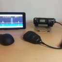
    Very nice project. Can you give us a short list of used components?

    Yes sure, here is the bill of materials:


    1 ADALM-PLUTO SDR

    1 Leo Bodnar mini GPSDO

    1 13cm Volks-PA (out of production)

    1 2.4G ZigBee band pass

    1 2W SMA-JK coaxial attenuator 6GHz 50ohm 20dB

    1 Step-Up converter 28V / 150W from CN

    1 Step-Down converter 12V / 5A from CN

    1 Step-Down converter 5V / 5A from CN

    1 Bias Tee for the LNB from OPA-Design

    1 Network adapter Micro-USB (OTG) ICY BOX IB-AC510

    1 ACS512 5A Hall Module

    1 LM3914 Display Module

    1 Semi rigid SMA cable

    1 N to SMA connector

    1 SMA T adapter female, female, male

    1 SMA 90 degree female to male adapter

    5 RG316-D SMA male to SMA male pigtail cable 6 inch

    2 RG316-D SMA male to SMA female pigtail cable 4 inch w. mount

    1 SMA female to F male adapter

    1 SMA female to SMA female adapter w. mount

    1 F female to F female adapter w. mount

    1 Cinch connector + plug

    1 LED 3mm w. mount

    1 CAT5 short cable 4 inch

    1 IEC 320-C6 AC connector

    1 Anderson Power-Pole DC connector

    1 Fan 40x40x10mm DC12V w temperature control circuit

    1 Neutrik Ethernet connector

    1 Aluminum enclosure

    1 Power cord IEC 320-C5

    1 BS170 FET

    1 BAT41 diode

    1 100n capacitor

    1 470R resistor

    1 opto coupler LTV 354T-SMD

    1 micro usb power cable 6 inch

    1 mini usb power cable 6 inch

    1 Meanwell sps 12V / 2.1A (25W)


    Some cables, bolts, screws and misc. parts


    ...

    The latest model of the BU500 has a detection of the input signal from the transmitter. At no input the LO is switched off.


    You should always use a 2.4G band pass filter between the output of the BU500 and the power amp, independently of the used LO frequency. A notch for the LO as well will be the ultimative solution.


    Mike

    You are right Heiner DD0KP, but i am at Ibiza and Mykonos for holidays where it almost never rains :P


    For my setup at home i did not find a perfect solution for this problem. The LNB rain protector from Amazon is not quiet good enough I think.

    Your cover seems to be easy to assemble.


    73, Mike

    This is my homebrewed QO-100 portable setup.


    The transverter is fully transceive on 70cm (RX/TX) and has an additional TCXO-RTL stick with the SDR-Console from Simon Brown for full duplex operation.


    All frequencies are GPS synchronized with 2 Leo Bodnar GPSDO units at 10Mc and 25.7Mc for the LNB.


    The upconverter is the BU-500 from HiDes modified for ext. ref. and with 2.4GHz cavity resonator and 20W power amplifier from SG-Lab. The p/s consist of 2 step down converters for 5V and 12V and a 150W upconverter for the 28V for the final amp.

    This is the complete all-in-one-box solution for Oscar-100.


    The modified SG Lab PA with extra hole and thread for the feedthrough capacitor to get the forward power for the meter.


    Everything is in the box, you only have to connect three cables to the LNB/Feed (RX 10G, TX 2.4G, Ref. 25.7Mc) and two cables to your UHF transceiver, in my case an Icom IC-9700.


    There is an extra 10 Mc output to sync the TRX if desired. For reception with the pc you have to connect an USB cable to access the built in RTL-SDR stick with 0.5ppm TCXO. This is optional for a larger panafall display but not neccessary to do qso's.


    The SDR Console is locked to the IC-9700 by OmniRig 2.0 so the VFO setting of the TRX changes the frequency on the console and vice versa for mouse access.


    A small fan is always running at 6V, in case of temperature rising above 60 degrees a temperature switch will increase the voltage to 13.8v for full cooling. A microwave coaxial relay will do the TX/RX switching of the down converted 70cm signal for the transceiver interface. The relay works with 28V so the level has to be adapted with 2 transistors to fit the range of the transceiver.


    This is my actual LNB/POTY design for holiday usage.


    More pictures at https://www.qrz.com/db/DK1ML


    Keep and stay always transceive on the sattelite ;)


    73, Mike

    DK1ML

    Hi Frank,


    thank you for that lovely project :)


    Could you please explain with a few words why you are using two RTL sticks and not just one?

    Is that neccessary for the beacon correction only?

    I am using almost a GPSDO stabilized LNB.


    When can we expect the image for the PI4 ?


    73, Mike

    DK1ML