

You need to have the right sort of lens in just the right position for it to work well. Too far in or out and it will no longer be at the focus. You should not be losing as much as 3 dB with a rocket LNB lens, perhaps a dB. Phase noise is a problem too. Was your bare LNB unmodified and the POTY one modified for an external reference?
Posts by G0MJW
-
-

G0MJW Yes, the same goniometry / math is also valid for offset dishes. An offset dish is nothing else than a prime focus dish but then another part of the parabola. The higher you get into the parabola, the larger the f/D. Although the illumination may look optically 'squint', the effective surface of an offset dish is equal to a 'prime focus dish' with the diameter of the width of the offset dish, see below.
Yes, I know this for a long time since I first came across the concept in the 1980s. What I don't know is if the curvature calculation still holds when working out the angle - I could work it out but... in my dish the curvature it rather shallow so it matters not.
-
I would suggest going down to 1 Ms rather than 1.5Ms. The quality that can be sent in 1 Ms H264 is really good. Even at 2/3 FEC. As the beacon is a fixed sequence, the coding could be done in advance and just a pre-prepared TS with all the optimisation thrown at it.
-
Bad audio on RX or TX? On TX there might be interference of course.
-
The idea is to have the feed illuminate the dish so it is -10dB at the edge of the dish. This is sort of compromise between efficiency and sidelobes. Ideally you want the whole dish illuminated evenly and nothing beyond. That's not possible as it violates EM theory, so -10dB is a realisable goal that gives good results doesn't upset physicists. A rule of thumb, not too much power blasting past the dish and doing nothing useful (over-illumination) and not too little of the dish used (under-illumination)
The good thing about rules of thumb is that like real thumbs you can bend them, but only so far. For the uplink you might want a little less than -10 dB at the edge. It's a trade off which is how the POTY works OK with most dishes 0.4-0.7 f/d - not brilliant but good enough, especially when RF power is plentiful.
The angle of the edge of the dish from the point of view of the feed depends on the f/d. Higher f/d is a narrower angle. 90 degrees is about right for common satellite dishes but you can work it out with a little geometry.
Well OK, you need complex geometry to get it properly but approximately is fine. E.g. for 0.6 f/d the make a triangle from dish centre to edge as the opposite and 0.6 x d as the adjacent. So that's 0.5 x d (as the centre to the edge is 1/2 the total dia) and 0.6d. Recall Tan(theta) = opposite/adjacent = 0.5d/0.6d = 0.833. Inverse tangent tells us theta = 40 degrees. That's a half angle so the feed beamwidth needs to be 80 degrees to fully illuminate the dish. I am not sure where 90 came from, except it's the value for a 0.5f/d dish and perhaps also account's for some of the liberties I just took in the calculation.
Think too much about this and you will tie yourself in knots. The bottom of the dish vs the top, but it's closer, near field, diffraction..oh no, hard sums, panic... At this point invest in some simulation tools or go and have a beer.
A helix with the same beamwidth should be easy to design but you must pay attention to the phase centre as it needs to be close to the focus. The 10 GHz focus alignment is most critical and with the LNB at the focus there is a good chance 2.4 GHz feed won't be optimum. I don't know where the phase centre of your Helix is but it's worth checking the design you plan to use with one of the reputable online calculators.
Mike
EDIT - following the link I see where the 90 came from. Remco did a more accurate geometry which I think is fine for prime focus but I am not sure it holds for an offset. Anyway, the idea is the same.
[Blocked Image: https://pbs.twimg.com/media/Dyd5IijXgAILiaP?format=jpg&name=medium]
-
A year has gone by .... ; -)
Time has a habit of catching up with you and then just keeps on going.
https://twitter.com/TheRealMike/status/1074326098752745474
John is to blame. Along with Robert Watson who suggested I tried CST student.
https://twitter.com/g4bao/status/1075456339005059074
Started with an ellipse which was the best, then tried circular with tabs/cutouts and eventually moved to the square version for ease of making. Most things I turn on my lathe are elliptical but that's not deliberate of controlled. This design progressed 19th-24th December ( I had to learn about EM simulation in CST first and then get past the limitations of the free version).
By the time we got to Christmas Paul had flattened quite a lot of old 35mm copper pipe and CNCd several prototypes. I am still using the elliptical version and Paul is still using the original that Remco later christened POTY.
https://twitter.com/TheRealMike/status/1077166330195951616
Here is the original RemcoCADTM
[Blocked Image: https://pbs.twimg.com/media/DvMy5GZXgAAcPNZ?format=jpg&name=4096x4096]
-

Great,
is the data transferred by hand, or is there a way to access it via the USB interface?
By hand - some of the never models may have a USB port that can be used for data but mine does not seem to be able to do this.
-
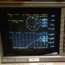
It gives you the real and imaginary impedance so you can plot your own smith chart - in the way like we used to.
Mike
Smith Chart for Excel is your friend in this..
-
I don't suppose anyone has accurate dimensions for the feed? I had a go at re-simulating and I am getting an excellent, linearly polarised response. I am assuming the placement of the feed and tuning screw are the magic I am missing.
-
Yes - I found my original simulation 20/12/2018 - no changes at all it surprised my and ran in the updated student CST.
Here is the 3D model - note the piston like capacitor - I probably need to adjust the disc dimension to have a stronger tuning effect but this was all a year ago.
The match is really good
So is the pattern
Smith chart says it all though
And that's confirmed by the axial ratio - this antenna is not circularly polarised.
What I will investigate is can it be made circular with more capacitance and a smaller disc. I had no success at the time but it was a year ago and I had only a day's of experience at the time.
-

Can I ask why you say the Bamatech is not circular polarized the web text says it is, I am curious as I know a few that have just bought a couple of these????
Adrian
The Bamatech patch works on the same principle as mine - two resonances in the right phase and amplitude relationship . This is achieved in that design through the offset tuning capacitor (screw) but for whatever reason it isn't showing them here. I built and then simulated a similar solution but I could not get it to work properly. Maybe with more tweaking but It was just one of several possibilities. James Miller, G3RUH designed a very good antenna for AO40 on exactly that principle and with a choke ring. It's well suited to QO100 too, but it is single band. Adding a choke ring to the POTY improves the backward sidelobes greatly, but it's not needed for TX only use.
A critical dimension with the POTY turned out to be the spacing, 3mm and less worked, by 6mm it didn't. I put this down to the effect of the waveguide that penetrates it. Maybe if a Bamatech like design used a smaller spacing it would also work. It would have the advantage of an easier to adjust tuning element. Tuning is very critical, so if you have one don't go adjusting the tuning unless you have the test gear to evaluate the effect. Otherwise you tend to get a well matched linear polarised feed.
If I can find an old simulation file I will add an image to show what I mean.
-
I won't buy as I already have two unmodified bards - so leave it for someone who really needs it (very fine price by the way) but I would appreciate a high resolution photograph of the modifications required.
-
However there are no clear sign of the double resonance around the test frequency. I did not find good explanation for this.
Can you look at it with a smith chart? This will hopefully show a loop. There is not always a double dip visible on a RL plot depending on how it is matching. Here is what mine looked lie on an xavna before and after tweaking.
-
A 2.4m dish and up to 50W but usually much less. 5W is more than enough for 333ks 3/4.
Mike
-
Here is the PLA prototype of my POTY hood. Will be printed in white ABS in the next few days and the patch will then be compared ...
Very nice. When you get time I have some Lilies to Guild.
-
-
Please compare with rocket and post-results -
It's timing.
Best option now is to forget the LKV373 if it wont work with your source. Use OBS record with an Nvidia hardware encoder sent as UDP to a pluto or send say 4Ms H264 from OBS to the nano to transcode with it's hardware encoder. There is also that €60 H264/H265 encoder box.
-
 Display More
Dear friends,
we have been busy over the past weeks designing a TCXO breakout board for the Pluto SDR.
The purpose is mainly to support people that are afraid of soldering these tiny 1.6 x 2.0 mm sized TCXOs. With the help of this ready-made breakout board modifying a Pluto SDR should be much more accessible to the average ham.
This project was supporting the purpose to teach my 11 year old son how to use KiCAD and getting him interested in our hobby. Most of the schematic drawing and manual PCB layout was done by him with only very little support from my side. I am very pleased about the result and the learning curve of my son.

In the attached KiCAD 3D images you get an idea how the final board would look like.
It uses the famous ABRACON ASVTX-13-C-40.000-I05-T (40 MHz, 1.8v, 0.5ppm) which is very stable when mounted away from the TRX chip, next to the FPGA. This is the VCTCXO version with frequency correction pin to set the clock to EXACTLY 40 MHz via a small SMD multi-turn potentiometer soldered onto the PCB.
This TCXO model is "The Model of Choice" for most Pluto SDR users on QO-100, due to its superb performance for NB transponder use. You can find many references about this TCXO model on the web with many happy users. The only limitation so far was, that this modification was only suitable for SMD experts due to the extremly tiny size.
See the attached photos of the PCB with the drawing on how this breakout board is supposed to be inserted and connected. It is just fixed at the right place with double sided scotch tape and then wired.
We are planning to have a first batch run of professionally produced boards made in a SMD fabricating house. This means we will be able to offer this PCB ready made with all components already factory soldered as a simple kit. The board size is approximately 7x15mm with some easy to solder pads for the wire connections.
A documentation and YouTube instruction video will be provided once first batch is available. (also including an "easy method" for removing the original XO from the Pluto)
If you are interested to be put on our waiting list and be informed about the upcoming availability of this PCB module you can write an email to plutosdrmod@gmail.com and please indicate in how many boards you would be potentially interested. We will then add you to the mailinglist and keep you updated about our progress.
73 de Oscar DJ0MY (and Daniel - my 11 year old desginer)
You have a clever son. This looks a neat solution for the SMD challenged.
I would advise against using the tunable TCXO. The stability may be better with a non-tunable one and any frequency error can be corrected through adjusting the pluto offset setting. This setting is held in flash and retained on power cycles. Also be aware some TCXOs tuning voltage moves the frequency in discrete steps so you will find setting it exactly not to be possible for those devices.
Mike
-
I had to use an OTG power cable with a separate DC feed. The current required was too much for the pluto.