Posts by DF1QE

    Somehow my entry from September disapeared, so I post it again :


    After my Oldschool Converter project I developed and build an other tiny converter 739 MHz to 144 MHz based on some earlier publications I found in the net.

    It works excellent for receiving Oscar100 NB transponder with a 2m RX.


    I wrote a complete report and building instruction for it.

    You can find it at : https://elektronik-muenster.de/viewtopic.php?f=17&t=34


    Sorry, german language only.

    But there are lots of pictures an shematics also for download so everyone should it find interesting.

    In other case "deepl" helps :)


    73s

    Armin DF1QE

    PA3FYM : Hi Remco !

    That's why I wrote "new (?)"


    But ok, let's say : you won :)


    Anyhow, there is some difference.

    As I saw in your Twitter picture, you just disconnected one side of the x-tal and directly connected it to the F-socket.

    I don't think the x-tal works optimal this way.

    I did some experiments until the x-tal was in optimal resonance.

    In the Diavolo quad I modified, I even mounted a variable C to "tune" the x-tal.


    But to all of you who did that before : Why did noone post it here ?


    73s

    Armin DF1QE

    DL5MGD Hi Andreas !


    Uhhh, not a good idea ...

    The x-tal needs this capacitive load to work on the right frequency.

    And actually the coax input needs a termination, at least a nearby one ...

    Ok, if you didn't implement the resistors, you have the high capacity of the coax on one side of x-tal,

    but then you need at least half the capacity (6p) on the in pin to get the x-tal in a good resonance.


    73s

    Armin DF1QE

    Sorry Remco, I cound not resist this wordgame in the subject :)


    So Folks, here's a new (?) idea for injecting an external TCXO, which I successfully tested.


    Just leave the x-tal where it ist, disconnect the LO out pin of the PLL-Chip, and inject the external LO at the x-tal.


    I tested succsessfully this method with 2 Diavolo Twin V2 and one Diavolo Quad V2.


    This method has some advantages :

    you don't have to remove the x-tal

    you can easily go back to internal LO (original)

    the external LO signal will be filtered by the x-tal

    easy to implement


    so many advantages :)


    The value of R1 in my shematic determins the sensivity and optimal level of the external LO.

    With 820 Ohm at a RT320M chip it is optimized for 1Vss LO input.

    For other levels you should make your own experiments.

    The value of R2 in my shematic depends on which impedance and coax cable you use.

    68 - 82 Ohm is fine for 75 Ohm systems.

    47 to 56 Ohm is fine for 50 Ohm systems.

    But this value is actually less important.


    Note:

    This method is not useful for (older) NXP chipsets.

    Therefor you better take a look at Remco's Subject : other-method-to-inject-external-ref-into-lnb


    73s

    Armin DF1QE

    @pe1hzg : I won :)


    Take a look at : New ATV Converter for Oscar 100 WB Transponder


    VY73

    Armin

    I have been considering prototype-ing something like this with a few changes:

    To be fed from the IF output, not external power supply;
    Allow it to be fed from 18V;
    18V DC power from the IF output passed-through to the input;
    144 MHz filter removed, or changed for 1335 MHz (1335 = 740 + 595 MHz)

    This way, one would have an in-line converter that I can put in-line between LNB and sat receiver, and which will convert the WB passband to a frequency range the sat receiver accepts. Because the sat receiver supplies 18V, the LNB would switch polarity.

    PA3FYM : Hi Remco !


    Yesterday I modified an older Divavolo Twin LNB.

    It was what I call in my reports the V3. (not found often)

    I did that as help for another OM.

    It has a complete different design compared to modern LNBs.

    For each channel works a seperate PLL & Mixer chip, but with a common 25 MHz X-tal.

    The chips are TFF1014HN from NXP.

    In an NXP short form application catalog I found exact this design.


    So I started my usual methode to find the in and out pins.

    25 MHz injected to one pin and monitored the other pin if they come out.

    And right the first test was fine.

    For some reason, I don't know, may be it was the RF sense of my body :) , I twistet the pins and what wonder : The 25 MHz were also transfered, with the same quality and level.

    Another wonder was, that one pin had a few volts DC-Level, the other not.

    It was not possible to follow the PCB tracks, so I assume one pin is capacitive coupled.

    So what type of Oscillator ist that ?

    The answer is simple : It must be a push-pull oszillator.

    https://www.google.com/search?q=gegentaktoszillator

    This oscillators are fully symmetrical an were frequently used for high frequency x-tal oscillators.

    Now it makes sense, why there is no specific in- and outpin.

    They remind me to my old pirate radio transmitters I build 45 years ago :) 2xCV6 or ECC85 :)


    But the thing why I write this to you is : Now your whole thread about symmetrial feeding the LO makes sense.

    If inside the chip, the design continues to be symmerical, it's sure that symmtrical feeding improves the singnal quality.


    I tested both feedings asymetric and symetric, and the signals at the x-tal pin were extreme better with symetrical feeding with a transformer.

    So again I must say thanks to you for this great idea !


    But for all others : Keep in mind, the symetrical feeding is important for this type of oscillator only, othes work better asymetric.


    I documented all with photos and will write a report about the modification as soon as find the time.


    And BTW, I found a perfect FXC for a trafo : the inductivity found in an old GEDU2411 Antenna wall plug from Hirschmann.

    With windings it has exact the size of the HC49 x-tal and it has a big inner hole to take enough windings with good isolation.


    73s

    Armin DF1QE

    Hi Leonid !

    Thanks for your comment.

    Hmmm, interesting idea ....

    I never checked that out.

    I'm sure it depends on the type of modulator.

    Older versions had free running oscillators, but I saw newer ones with a x-tal based PLL.

    The newer ones should be stable enough to act as LO for ATV converting.


    But to be honest, why doing that if one can have it in a single 5x7 mm SMD case ?


    73s

    Armin DF1QE

    Hi Folks !

    Here I am again.

    Some of you may know me from my activities in the NB-Transponder forum.

    So, based on my former converter projects, I developed two new converters 745 to 1340 MHz.

    The highlight is, they do not even need an extra powersupply. They were feeded from the Sat RX :)

    So I called them "WB Konverter inline" V1.1 and V2.0.

    V1.1 is the stripline filter version and you find it here : https://elektronik-muenster.de/viewtopic.php?f=17&t=37

    V2.0 is the SAW filter version and you find it here : https://elektronik-muenster.de/viewtopic.php?f=17&t=38

    So all you need is a regular PLL LNB (no need to stabilize), the converter and a regular SAT RX which fits the digitalparameters.

    I hope you like this info.


    What comes next :

    A Triplexer for feeding LNBs with 25/27 MHz, and 12/18V from a single 12V Supply

    A converter 739 MHz to 28 MHz that really works (with no image problems)

    A "all in one" solution : 25/27 MHz Ref + NB-Converter + WB-Converter in one box


    So keep tuned ... :love:


    VY73

    Armin DF1QE

    Nice experiment !

    But why such a big ferrite ?

    You have to transform ony miliwatts.

    There are nice ferrites which are not bigger than the original crystal.

    So you do not have to make a gap in the case.

    I used a simple 1-hole ferrite with 3.5 mm outer diameter.

    (see pictures on #18 this thread)


    73s

    Armin DF1QE

    Don't waste your time with si5351.

    I started with the same begin this year and wasted weeks for getting it work.

    As George and Dave already said : The internal frequencygeneration is the problem.

    The si5351 produces sideband signals.

    In the regular use, for examle on shortwave, they are not a problem.

    But we multipy this refecence signal X 390 in the LNB.

    This together builds the problem.


    You should take a look on my solution with the indoor TCXO :

    https://elektronik-muenster.de/viewtopic.php?f=17&t=12

    This is how all my LNBs work stable and clean now.


    73s

    Armin DF1QE

    Hi Adrian !

    The photo you postet does not show a TCXO.

    It's just a simple x-tal, nothing more.

    If you follow the striplines you see the typical x-tal design with the 2 ballast Cs.

    And the x-tal case is just connected on 2 pads.


    73s

    Armin DF1QE

    Hello Jan !

    Thanks for your comment.

    Well as I wrote at the end of my report I am about to do the same.

    So we will see who is first :) ....

    The DC feeding and feedtrough from a receiver is a really nice idea.

    May be I will implement that as an option.


    73s

    Armin

    Hello Achim !

    Thanks for your comment.

    About the LO harmonic I agree. In some older RF SDR designs they even use just switched mixers with digital components.

    But anyhow it also mixes with the harmonics, so an input filter on 739 makes sense to keep unwanted products away.

    And about the output matching : That's why I attached the diplexer and the dump resistor to the mixer output.


    73s

    Armin DF1QE

    Hello Sat-Fans !


    Update : After some requests, I offer some semiprofessional, homemade PCBs for this Konverter now on ebay.

    Look at : https://www.ebay.de/sch/armin_graewe/m.html


    After my converter "oldschool style" I developed and build another simple, more up-to-date converter 739 MHz to 145 MHz with just 3 active RF-components. I named it "NB-Converter tiny".

    It works excellent for receiving Oscar100 NB transponder with a 2m RX.


    I wrote a complete report and building instruction for it.

    You can find it at : https://elektronik-muenster.de/viewtopic.php?f=17&t=34


    Sorry, german language only.

    But there are lots of pictures an shematics also for download so everyone should it find interesting.

    In other case "deepl" helps :)


    73s

    Armin DF1QE

    As promised I made a test with 2 equal LNBs, one feeded Osc in-Pad only and one feeded Osc in- and out-Pad.

    Damned, Mc Murphey was my friend in this test ....

    I had 3 very cheap Single LNBs from Megasat "single gold" on stock.

    One of it I shot to death in an earlier experiment.

    They were extremely static-sensitive at the antennas, because the antennas are directly connected to HEMT-FETs.

    Ok, so 2 left for this experiment :)

    I wound a ferrit bead trafo with enamelled copper wire as PA3FYM described and mouted it like the upper described Methode 1a.

    First Tests in the lab gave good results, but then sudden the PLL stopped working at all .... So what happened ?

    Mesurements showed something horrable : The isolation between primary and secondary windings got bad and so 12V powersupply was directly lead to the oscillator IC. Ouch !

    So here a warning : Methode 1a is very dangerous ! You have to assure a good isolation between primary and secondary winding.

    So the second LNB was shot to shot to death too :(

    Ok, no problem, they are cheap and I ordered another 3 LNBs.

    Well, one LNB left on stock so let's do it again.

    This time I smoothened the sharp edges of the ferrite bead, inside with a drill and outside with a file. Then I wound it with 0,1mm cotton sheathed enamelled copper wire. Actually I would prefer teflon coated wire, but I do not have it so thin. I made some isolation measurements and all was ok. Then I mounted it in the LNB. This time it works fine and I had to wait for the delivery of further LNBs.

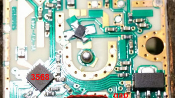
    When they arrived the typical shock came on me as to many other hams who modify LNBs ... It was the same Package but a complete different design.

    Even the chips were different. The old PLL was with a 3566 IC, the new one with a 3568 IC.

    To keep my test comparable I had to modify equal LNBs ...


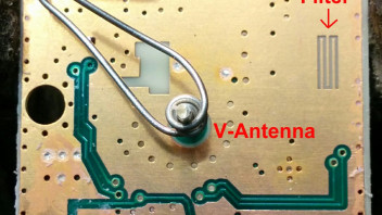
    This is the original LNB antenna side with antennas grounded.

    (see the very interesting designed filter, I've never seen it this way before)


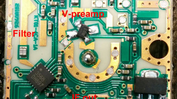
    And the component side with removed x-tal


    So again I wound 2 more ferrite beads as described before.


    And mounted it as above.


    At both LNBs I placed a 1n chip C at osc.in pin for DC decoupeling.

    In one LNB I connected the other end of the winding to the osc.out pin and in the other LNB I connected it to ground. All x-tal ballast Cs were removed.


    Then both LNBs were succsessively connected to a triplexer to which I feeded 12V DC and 25 MHz from my "indoor TCXO" which I desribed in other article in the forum. Between TCXO and triplexer I placed a 60 Ohm variable attenuator to give diffrent 25 MHz level. The output of the triplexer lead to an Avantest spectral analyzer.


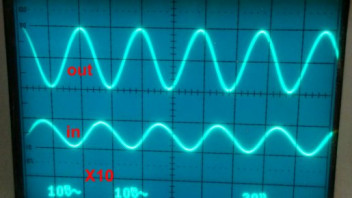
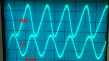
    This were the signals found with an oscilloscope at the osc. in and out pins at the "symmetrical" version.

    No wonder that the level on the in pin is lower because the level on the out pin (other side of the transformer) is in 180 deg. phase shift and works against the transformated signal.


    And this were the signals found at the in pin and to ground version.

    The out pin is left open.

    I find it interesting that the phase shift differs from 180 deg in this version.


    Anyhow to get the pll to lock, in the symmetrical version much more Ref level is needed. And to get a clean noise- and jitterfree signal I even had to remove the internal pi attenuator in the indoor TCXO.


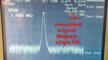
    Here's an analyzer screenshot of the unmodified LNB with x-tal

    (sorry I forgot to set the marker right, so the correction)


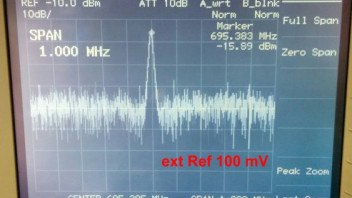
    That's the symmetrical version with 100 mV ext. Ref (at the coax)

    A lot of noise to see !


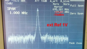
    And here the same with 1V ext. Ref

    Nice low noise and clean signal, as it should be.

    (sorry I forgot to set the marker right, so the correction)


    The "in pin only" version looks the same, but with much less drive power needed.


    So now to the real test in the dish :


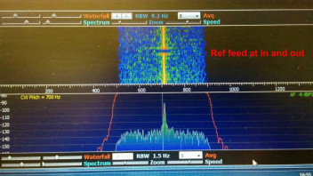
    The Oscar100 CW-Beacon with the symmetrical ref feed.


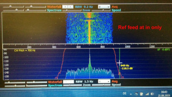
    And the Oscar100 CW-Beacon with the in-only ref feed.


    The "in-only version" signal might look sharper and the noise lower, but that's not true.

    This pictures are momentary captures. When I watch them for a longer time they are very equal. Also all other signals on Oscar100 look equal.


    So here is my fazit : At the LNB Type I modified, it makes absolutely no difference in signalquality to feed ref symmetrical or not.

    The only difference is, that the symmetrical feed needs much more ref power.


    Anyhow it ist still a very nice and easy idea to place a trafo for decoupling the ref. I will keep using the in-only methode.


    Does anyone know where to get 0.1 or 0.15mm teflon coated wire ?


    best 73s

    Armin DF1QE

    Ok, don't take me wrong.

    I did not say that it could not be right.

    But I'm a man who likes to understand why things are the way they are.

    And the question is : Is it right for any chipset ?

    That's why I said someone schould check it out ...

    Anyhow, if I get the time next days / weeks I will do that and let you know the results.


    73s

    Armin