Posts by pe1hzg

    I found your signal even more useful than expected, while testing link margin during a thunderstorm. I know I lost at least 15dB at its worst, and that happened while the streets were still dry. I could "see" the thunderclouds drifting towards the sat path. When the rain started, signals went up ;)


    Using WebSDR, I saw that my own signals were not attended as much which is strange (2.4 is the max water absorption frequency ?!?)


    Having longer signals at a level would be useful. "zero" is short to measure.


    Is 0dB the beacon level? I don't think it is, but propagation is strange right now.


    I any case, this is useful, but perhaps t needs to be there structurally. Good stuff!

    Without wanting to play my own harp, see https://forum.amsat-dl.org/index.php?thread/2856-transverter-pe1cmo-and-kuhne-down-konverter/&postID=9489#post9489


    I don't know if Megasat has a good representation in the UK, the BRexit has caused a deep ditch to the mainland but let's keep the forum technical please!


    However, brand and type doesn't matter that much. Keep in mind that if you buy a certain type of LNB, and you order the same type 3 months later, you will likely find completely different electronics inside. In that regard, what does matter is to "buy a few at once". If you break one, you have learned the construction and the next one will be easier to modify\; you also have "one to look at" which I find, helps a lot.


    The key is to get a LNB with crystal reference. The good news is that these are cheaper than older models with DRO. My suggestion is you buy a few, open one, if it is a DRO-type, send the other ones back unopened. Personally I find it difficult to ind DRO LNB's these days; PLL is much more common

    Also, something that is not covered in that document, and I had problems with, is cutting the wiggly line going to the voltage regulators and adding an SMD inductor. That wiggle line is enough inductance to block the IF going into the regulators, but is not enough to block a 25M signal, and the decoupling caps at the input of the regulator were eating all of my 25M reference preventing the LNB from locking. Once I added an external inductor (820 nH IIRC) it locked just fine.

    The proper way, IMHO, is to make a parallel resonance circuit on 25 MHz. That will keep the reference where it is supposed to be.
    Personally I use 150nH and 270pF. Note that with SMD these can be "stacked" making it easier to find space for them.

    It is sunday afternoon and it shows, on the spectrum waterfall. Carriers come and go, drift all over the place, people calling "test... test".


    We've all seen it and we've all cursed it, but what is someone to do who just want to test his signals? Aren't callsigns not given not just out of disinterest, but also to avoid being called for QSO? If I want to test, where should I test?


    I wonder if it makes sense to set aside a small segment (20 kHz or so) just for testing. "if you must test, test in the test segment; no QSO in test segment",


    I guess most of us know that the most often used feature of a terrestial FM repeater is testing. "click-boing": doesmy radio still work? I think the same applies on our bird.


    I guess the good news is that the test signals most often happen during EU daytime. That means it's humans doing this, and perhaps these humans can be guided


    Just a thought,


    Geert Jan

    Zuerst den Quarz im LNB Ausbauen, mit zwei Lötkolben, nicht zu kalt, dabei auf den Kondensator an einer Seite des Quarzes beachten das der nicht weg fliegt.

    The PCB material has very good heat transfer properties, and the pads loosen easily if stressed.


    I find I need to reproduce chernobyl if I want to remove components while leaving the PCB in place, because the heat gets transferred to the metal casing. Un-screw the PCB and lift it a bit, and you will see you can work with much more civilized heat levels to lift parts.


    Make sure you use ESD measures when working on this and don't bend the antennas.


    The diavolos I ordered recently have been through a design change and use a different PCB, but the principle is the same.


    I find that it is beneficial to order a few LNB's at the same, if I ruin one I at least know what it looks inside and working the next one is easier.


    73, Geert Jan

    Actually, you can't use the TV splitter modelled because it does have filters in it (it has to, because otherwise LNB noise would interfere with TV signals).


    Strange as it may sound, the one you want is:

    This is "just a TV splitter" but if you open it, it actually has a transformer inside to do the impedance thing correctly. You will see that it passes DC on all three ports, so voltage supply for the LNB "just works". Disadvantage: this splitter uses Belling-Lee connectors, though adapters to F and BNC exist.


    Note that this splitter really is different from the typical "plastic" splitter which uses resistors. Check your ohm meter.


    I would like to stress that this works for the specific use case you have. NB and WB have different polarisations, so this trick can't be used to receive NB and WB on the same single LNB. For those cases, I recommend dual LNB's, I have good experiences with the Megasat Diavolo Twin LNB, giving me two independent ports can can do each polarisation as I want for the experiment du jour.


    Geert Jan

    While making adjustments to my station I must admit being guilty to triggering LEILA (I'm sorry, guys!).


    But, I found that I didn't hear LEILA, I only saw LEILA on monitoring. So I investigated closer.


    When sending a carrier, my radio sends a carrier on "carrier frequency" of the USB signal. Using USB means that the modulation will be above the carrier frequency.


    When LEILA triggered, I found it sends a carrier on the frequency it "discovered" and a lower frequency. That means the LEILA signal will be outside my filter, which explains why I didn't hear it.


    My question: why does LEILA use the "discover frequency" and a lower frequency for signalling instead of using a higher frequency so it would be in the passband of my receiver?

    Hi,


    I recently purchased https://www.ebay.com/itm/332389156868

    This is an OCXO, so it is with an oven. It takes 90 seconds to stabilize (and the casing gets warm as the oven heats up).

    I got these as frequency reference for by QO100 setup if GPS isn't available or if I want to test something quick - GPSDO takes more time to synchonize.


    Mind you, this thing does 10 MHz, not 40. But if stability is an issue - give it a spin!


    73,


    Geert Jan PE1HZG

    As to "S9 signals": when looking with the WebSDR, the noise level is roughly -92 dB and the peak of the CW beacon is -77dB. You are not supposed to be stronger than the beacon so the maximal S/N ratio you are allowed to make on QO100 is 92-77 = 15dB. According to IARU, 6dB is one S-point, so the maximal S-point raise is 2.5 S-point. This is the *increase*.


    The question is what the S-level is of the noise floor In order to have signals that are really S9, the background noise must be at least S6. That is mighty uncomfortable. You will find that your receiver works much better if the noise level goes further down, on my setups it's typically S1-S2. I strongly suggest you experiment with this, there is another discussion about this on the forum, you will probably find that your receiver works much better if you lower the noise floor a little (for one, it will help reducing reciprocal mixing with the background noise)


    And with a S2 noise floor the best report is S4.5. You can still report whatever you want (and just add 5 S-points if you want). It really doesn't matter. And 15dB S/N is quite comfortable, "Hi-Fi signals".


    The IARU also defines how much signal S9 is. On HF, it is -73 dBm. On VHF and higher, it is -93dBm. And with your LNB, I am pretty sure you won't be able to measure this, I think that very few people on this forum can really measure signal levels on 3cm. Also keep in mind that the LNB has a lot of gain and this amount of gain isn't calibrated either (but it is enough that the LNB will define the noise figure of your system unless you're really unlucky. Consider this a plus, because these crap LNB's are pretty darn good these days!)


    Keep in mind that very, very few rice boxes really do 6dB per S-point as per IARU spec. I have seen several transceivers where the difference between S1 and S9 is less than 20dB (!). Try to make a decent report using lie detectors like that.


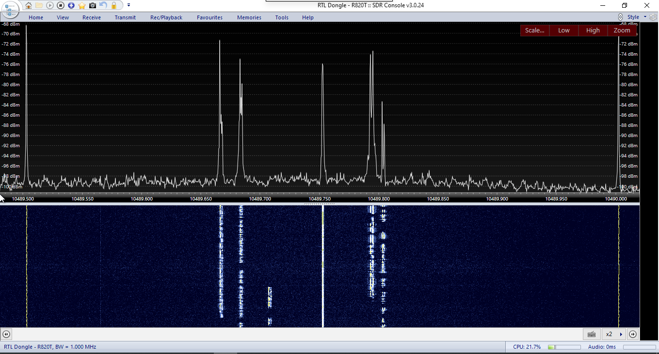
    Where does this lead you? I think a S-report is pointless. What is useful, is to use the perseus to report the signal level above the noise (and for those reading this who don't have a perseus, I'm doing passband monitoring with a RTL-SDR stick and a PC with SDR console, which is pretty slick. If you want to give a good report, use S/N above noise and do away with S-reports. You will get 59 from the other station and you will know that he is probably struggling too getting a decent report.


    EDIT: addition. What I find useful is to browse to the Goonhilly SDR, set the signal strength plot to "slow" and then use the WebSDR to tune to signals. I think you will find the signal strength history of the slow signal plot to be very educational. It is too bad that this isn't the default - really should be!

    For those wondering, the goonhilly crew is having bad luck and is now reporting issues with the GPS antenna. The GPSDO is still stable but a few kHz off. Maintaining some repeater sites myself, I feel for the crew because Corona generally makes access to these sites very complicated if not impossible. The webSDR is still very usable but keep in mind it is a few kHz off.


    Status info is given on the info on top of the page (yup, the info I skipped too)


    This actually gives an interesting side effect. When looking at the upper beacon, I always heard an extra carrier (have the same problem in my setup). This is probably related to the reference frequency sent to the LNB. Because the reference is now slightly off, the reference harmonic and the beacon signal are now on different frequencies. You may want to study the upper beacon while this situation persists.

    I'm using CH3+8 (2.4GHz) and 5GHz as well. My Antenna is 10m away from my house. No problems so far using the NB transponder (2W+POTY+1.2m offset dish).

    WB and more power could be different...

    Keep in mind that with the higher wifi speeds, the channels are wider and hence channels overlap. If you are using channel1 then channel 2,3 are unusable. Industry practice therefore is to (only) use channel 1, 6, and 11. WIth QO100 activity that leaves channel 6 and 11. Use of channel 3 and 8 is like transmitting on 145.505: you block 145.500 and 145.5125.


    I realize that signals are local but I still remember when I was the only one with wifi - these days I see 30-40 SSID's easily and unfortunately not all of them use this scheme. wifi on 13cm in city areas is a zoo.


    I realize this is out of scope for this forum but if people tinker with these settings they might as well know.

    Not intending to kick up a lot of dust, I am asking:

    In some local QSO's there has been, for a number of days, a discussion on QO100 frequency accuracy.


    On my own station, i find that I typically need to tune 70-100 Hz down to be on frequency. I blamed that on my own equipment (even if every single component is GPS-locked), though I wasn't sure where it would come from.

    All that, until I heard in the discussion that others are reporting same.


    People using the beacons for reference are OK and don't report anything.


    We know that the LO in QO100 is spot-on (see the NDA discussion elsewhere).


    Without wanting to blame others: can anyone confirm the correctness of the frequencies of the beacons?

    I know there have been issues in the past and realize that maintenance in Corona days is a challenge, but a brief "yup, we know" helps me to stop searching my own kit.


    There also have been discussions on a small offset in BG7TBL references, but that offset is constant and for this issue, the numbers don't add up, so I don't think it is that.


    Clue appreciated,


    Geert Jan

    Sorry for playing my own harp but as to frequency stabilisation, have a look at this discussion on the forum: 432/28 MHz transverter from transverters-store.com


    As to the Anglian converters, they are good but parts may be an issue.


    Keep in mind that for QO100 the dynamic range is limited. On WebSDR, the beacons are less than 20dB above the noise floor and stronger signals than that yield QSL's from LEILA. My suggestion is to focus on reciprocal mixing given the relatively high noise floor. In my experiments, I find that receivers that are quoted to have good LO's give me better signals.

    If heat really is an issue, my suggestion would be to screw in another connector, say a F-BNC adapter, before soldering. This brings a few advantages:

    • It centers the middle pin while the dielectricum of the F connector may be temporary more flexible because of heat
    • It provides additional cooling at the end of the connector that isn't soldered on

    Be surprised how hot such an adapter gets after soldering!

    Würde aber trotzdem empfehlen das Dämpfungslied nicht hinter dem LNA, sondern hinter dem Konverter bzw. direkt vor den RX einzufügen...

    Wouldn't this cause unnecessary reciprocal mixing between the noise floor and the LO of the converter? The LNB defines the noise figure, and any attenuation in an IF frequency should not matter unless the attenuation is so high that the noise floor cannot be detected anymore..

    Hi,


    I'm using the Goonhilly WebSDR to monitor my transmissions. Unfortunately, something has changed:

    It used to be that if you put your mouse pointer inside the frequency bar, you can use the scroll wheel of the mouse to change frequency.


    This was cool, because I had re-programmed one of those "USB volume knobs" to generate generate mouse-wheel events. This means I could use the knob to tune the frequency I was tuning to.


    But something has changed. Putting the mouse pointer inside the frequency bar and clicking no longer lets the wheel to be used as frequency adjust; instead, the web page scrolls. That makes the knob useless.


    Has anybody found a way to make the mouse-wheel work again for frequency adjustments?

    Update: because of the current Corona-situation in the Netherlands, the Dutch government has come with new struct rules under which doing JOTA is not feasible for us. We will therefore not be active with JOTA on QO100 this year.


    Hopefully next year QO100 will still have TWT's and we will be able to create some activity then. So it goes!

    Hello,


    Last year we used QO100 during Jamboree On The Air (JOTA). We made only a few QSO's but the scouts enjoyed them.

    This year JOTA will be 16-18 october and I am considering setting up the QO100 station again.


    This year, we have Corona restrictions and there will be fewer stations. Additionally, stations doing JOTA may decide not to set up their QO100 station because of lack of space in the scouting hut (distance rules) or less hamradio operators to operate the equipment.


    Still, I am considering setting up the station.

    My question on the forum: will there be other JOTA stations in 2020? Doing the effort makes no sense if there are no other stations to make QSO with.


    Plans can change if Corona restrictions change obviously, and rule changes in PA0 are, eumm, erratic.

    But I only want to do the effort of setup if if there are other JOTA stations planning to become active.