Posts by DF6LO

    There is no restriction on the actual mode used, but the transmitted or occupied bandwidth shall be below 2700 Hz.

    DB2OS

    Hi Peter, Most (all?) of the ADALM-PLUTO user are occupying 3 kHz of bandwidth in SSB. I don't know the ADALM-PLUTO and maybe a smaller bandwidth is not adjustable. Wouldn't the band plan have to be adjusted in this point?

    73 de Matthias

    Thanks a lo Alex!

    I didn't manage to find that out by using all my digimode tools. And Google was also not helpful .. or I used the wrong search method :/;)

    73 de Matt

    Well, English seems to be the most common language to communicate among radio amateurs. Since many are not first language speakers, there will be one or the other grammatically unusual sentence order, and also with the correct designation of components there are misunderstandings. But this should not be a reason to make fun of it. Most of the time the actual meaning is understandable, isn't it?

    I'm fully aware about the mandatory full-duplex operation requirement. Thats why I mentioned the following ... "For monitoring my own signal I use one of the WebSDRs." .. and thats what I'm doing infact. It's helpful to check the uplink signal strength.


    Transceive operation is much more convinient (It's annoying to listen to your own delayed signal and when you don't use headphones it causes echos) and it's a must when you want to use WSJT-X for digital modes with an external soundcard like the SignaLink USB together with the FT857 ... at least I didn't find an alternative solution.


    Well ... but digital modes might trigger the next clash8)

    "Compared to a LNB directly at the focus of the antenna (without the dualband feed) I loose 3 dB of SNR."


    I managed to re-gain the 3 dB of decreased SNR by installing a low noise preamplifier from Kuhne electronic at the feed.

    Now I can observe the noise floor of the transponder with about 2 dB and even very low SSB signals are easy to copy. No difference compaired to the WebSDR anymore. :)

    (with a local spurious signal at 432 MHz)


    I observed a strong disturbance of the GPS reception with a lost of PLL lock of the GPSDO obviously caused by the much stronger IF signal due to the pre-amplifier and perhaps harmonics. The 75 Ohm match at the LNB and the components in the outdoor cabinet (splitter and DC feed) might be bad too which lead to standing waves and unwanted emission from the coaxial cables. I had to decouple the GPS antenna cables from the LNB cables and I installed a low pass so called LTE filter. The GPS reception is back to normal now.

    CU on QO-100

    73 de Matt, DF6LO

    An example: My QO-100 setup


    Main goal was to achieve a transceive operation with a 70 cm TX/RX, my already existing FT857D. I wanted to avoid tuning in procedures, and the digital mode equipment setup with my FT857D should be usable for FT8 and other modes too.


    The SG Lab. transverter is stabilized with a GPSDO at 10 MHz and the modified LNB is fed with a 2nd GPSDO at 25.7884615384615 MHz to get a transceive setup: -> 10,489.550 MHz - (25.7884615384615 x 390) MHz = 432.050 MHz


    TX: 432.050 - 432.300 MHz to 2,400.050 - 2,400.300 MHz

    RX: 10,489.550 - 10,489.800 to 432.050 - 432.300 MHz


    The modified Megasat Diavolo Twin LNB sits behind the 55 cm offset dish in a waterproven box. I cut the waveguide and mounted a short semi-rigid cable with a SMA plug, to feed the RF input directly via a suitable 1 pF microwave SMD capacitor. There are in total 40 cm of 3.6 mm semi-rigid cable and 60 cm of 10 mm Hyperflex cable between the BAMATECH dualband feed (DJ7GP) and the LNB. Compared to a LNB directly at the focus of the antenna (without the dualband feed) I loose 3 dB of SNR. So this is the compromise I accept for this architecture.


    The CW beacon generate S7 at the FT857D and the SDRplay (running SDRuno) shows -105 dBm with a noise level at -135 dBm (7.5 Hz resolution bandwidth). The difference to the WebSDR is very small. Only the very weak signals which you hardly could recognize at the WebSDR too, are difficuilt to copy.


    The transverter and PA from SG Lab. are in an outdoor cabinet (Outdoor Box 1). Some relais and attenuators are built in to switch between high and low power. Considering the attenuation of the cable between the outdoor box 1 and the feed, delivers 200 mW (for digital modes) or 10 W to the feed. 10 W generates a signal similar to the BPSK beacon level.


    On the RX path a variable attenuator brings the noise level to S0 at the FT857D. The SDRplay is fed via a splitter and another variable attenuator. This is for the visual reception. Of course, the SDR can only be used to a limited extent in transmit mode because of the crosstalk directly into the SDR on 70 cm. For monitoring my own signal I use one of the WebSDRs.


    Power supplies for 24 V (PA), 12 V (transverter and LNB) and 5 V (GPSDO) are within the outdoor box 1.


    Just to get an idea regarding the effort. The overall expenses were about 900 Euro, not considering the already existing FT857D and some parts like relais, plugs, cables and so on. It took me 3 months to set this up.


    CU on QO-100,

    73 de Matt, DF6LO


    Thanks for the UCXlog recommendation.


    It's probably not only a matter of the logbook software :/

    ... but also the reliability of the QSO partner;)


    Still using Swisslog V5 and logged 24 QSO. Received until now ...

    - 3 QSL via LotW

    - 6 QSL via eQSL


    73 de Matt, DF6LO

    I think I got it ...

    (screen shots with courtesy of Thilo, DL9KCE)


    The experimental tool BEMFVDish.exe from DL9KCE (DARC website for member) verifies that the liniear calculation for the power flux density (PFD) assuming a far field situation can be applied even for smaller distances (under certain limits). Taking the exposure limit of 61 V/m into account lead to the following results.


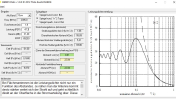
    DK8KW: 1.9 m dish, G=31.4 dBi, PEP=47,3 W

    => safe distance of 23 m (with respect to the center of the main lobe)

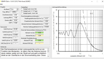
    DF6LO: 0.55 m dish, G=20.6 dBi, PEP=10 W

    => safe distance of 3 m (with respect to the center of the main lobe)


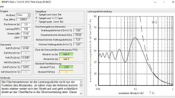
    DL9KCE's tool shows an estimation for the beginning of the far field (r0 = 2D²/lambda ("normierter Abstand"), D=diameter of antenna). You can find this as well for instance here http://www.radartutorial.eu/06.antennas/an60.en.html .


    Interesting to see is, that the bigger the dish and the higher the frequency, the larger the distance to the beginning of the far field region. Even more interesting that the maximum PFD (Smax) is higher for a smaller dish and lower power. See the oscillating PFD in the near field region.


    DK8KW: Far field starts at r0 = 56 m with PFD=1.66 W/m² (center of main lobe)

    -> level exaltation of about 41 at 0.1xr0=5.3 m

    => Smax=70 W/m² (not fully clear where)


    DF6LO: far field starts at r0 = 4.7 m with PFD=0.44 W/m² (center of main lobe)

    -> level exaltation of about 41 at 0.1xr0=0.44 m

    => Smax=175 W/m² (not fully clear where)


    My earlier assumption regarding the beginning of the far field region with r0 = 10xlambda = 1.25 m is not correct for a parabolic dish. So for DK8KW's setup the 60 kW EIRP is correct but not the PFD with S=3000 W/m² at 1.25 m.


    So actually you can't use the far field formulas but when you look at the diagram (BEMFVDish on the right) you notice that at 0.2 x r0 the deviation is very small. But for distances below that, one has to consider the near field and transition zone.


    Now at the end one have to consider the height of the antenna and the elevation of the main beam of 28.5° (for central Germany, see the sketch in post from DK8KW). I guess we can neglect the side lobes. Regarding the beam width I was too lazy to use the formulas but looked for online calculators.


    http://www.satsig.net/pointing…-beamwidth-calculator.htm

    https://www.tracking-antenna.d…as/beam-width-calculator/


    1.9 m dish, 2.4 GHz, efficiency 0.6, 31.4 dBi

    -3 db +/-2.39°

    -6 dB +/-3.39°


    0.55 m dish, 2.4 GHz, efficiency 0.6, 20.6 dBi

    -3 dB +/-8.27°

    -6 dB +/-11.7°


    -6 dB reduces the safe distance to half the value calculated for the center of the main lobe (see above).

    DK8KW: 23 m/2 = 11.5 m

    DF6LO: 3 m/2 = 1.5 m


    A little bit of trigonometry lead to ...


    DK8KW: Antenna height 2 m, -6 dB at (28.5°-3.39° = 25.11°) elevation

    => at a horizontal distance of 10.4 m the exposure limit is reached at a height of 6.9 m = (2 + 4.9) m


    DF6LO: Antenna height 1.5 m, -6 dB at (28.5°-11.7° = 16.8°) elevation

    => at a horizontal distance of 1.44 m the exposure limit is reached at a height of 1.93 m = (1.5 + 0.43) m


    ... or with respect to the center of the main lobe...


    => at a horizontal distance of 2.64 m the exposure limit is reached at a height of 2.93 m = (1.5 + 1.43) m


    So everything is safe with respect to DK8KW's and my contollable areas.


    DK8KW's setup with 750 mW -2 dB = 473 mW doesn't exeed the exposure limit at all.


    I wonder if the results of the current so called experimental tool BEMFVDish.exe will be accepted by the BNetzA.

    DH2VA: "... derive its effective gain in the direction to the uncontrolled area."


    That is what C stands for. But one need to know this for the specific antenna in use.


    So the calculation to prove that the field strength at the border of the so called controlled area is within the limit is quite complex. Especially when you take the variety of offset and prime focus dishes into accout. I'm quite sure that there is no real hazard but I wonder if anyone has already shown this in a comprehensible way.

    M0VKK: Sorry to say but I fear that is not right. The calculation must take into account the directivity or gain of the antenna.


    https://emf3.bundesnetzagentur…ang1_3%20(3)-13-08-23.pdf


    It's in German but the equations are universal and one can find this in the standard technical literature as well.


    r = safe distance

    C = attenuation for an specific angle with respect to the main beam direction

    Eg = safe limit of the electric field strength

    Hi all,


    Thank you very much for yor useful information. A possibly ARRL publication would be indeed quite helpful.


    DK8KW: Your sketch of the antenna setup and the so called controllable range or space is very helpful too. Actually that is right what I am looking for. Thank you very much for that. Thank you too for the info about Watt32. I first thought that Wattwächter was the successor of Watt32.


    Probably the figures of your calculation have to be modified because you stated to take the maximum allowed PEP of 75 W (- 2 dB = 47.3 W) into account but calculated with ERP. An antenna surface area of 2.8 m² (1.9 m diameter dish) leads at 12.5 cm wavelength to approximately 31 dBi antenna gain, assuming 60 % efficiency. 47.3 W at the feed of the antenna will cause an ERP of 60 kW! At a quite low distance of about 10 x Lambda = 1.25 m (far field assumption?) you will have a power flux density of round about S = 3000 W/m² (26 W/m² in 13.4 m).


    It looks a bit more harmless for my 55 cm dish (21 dBi) and 10 W PEP at the feed. 64 W/m² at 1.25 m.


    Your 750 mW - 2 dB will cause 600 W ERP and 30 W/m² at 1.25 m distance from the dish. So everything is harmless as well.


    I hope I didn't miscalculate in a hurry, so please rectify if necessary.


    73 de Matt, DF6LO

    DD4YR


    Thanks Robert, but I'm aware about the standard process which has to be send to the BNetzA (former RegTP).


    I should have been more precise with focus on QO-100 operation.


    Has anyone experience in calculating or measuring the field strength according the radiation pattern of a satellite dish? I flipped through the "Wattwächter" (former Watt32) antenna files and couldn't find anything comparable.


    73 de Matthias, DF6LO

    oe9wlj


    Hi Wilfried,


    Many thanks for your hints. 2300 MHz is the default for 13 cm in Swisslog V5 but I changed this earlier already manually to 2400 MHz without success.


    According to Robert/DL5GAC the RX Band should be irrelevant. Furthermore I can't edit this in Swisslog V5.


    Which logbook software do you use?


    73 de Mattias, DF6LO

    _____________________________________________________


    Hello Robert and SAT-Friends,


    I use Swisslog V5 and didn't get a single QSL confirmed via LotW yet. Just a few eQSL were confirmed. Input seems to be ok as shown here in the group.


    Were is my fault and what Logbook do you use?


    73 de Matt, DF6LO


    Details of a QSO uploaded to LotW: