

Hi Peter
mni tnx info. Octagon Web-site will not show the documentation for this stuff.
So Thank you very Much for detailed answer which will help me receiving es'hail-2 in the near Future
73s
herbert
Hi Peter
mni tnx info. Octagon Web-site will not show the documentation for this stuff.
So Thank you very Much for detailed answer which will help me receiving es'hail-2 in the near Future
73s
herbert
Hello!
I have a GPSDO system already in my shack. Based on the 10 MHz signal, I would like to generate a 27.8516 MHz LO for my already modifed LNB (the XTAL has been removed).
Does anyone know a usable DDS board to generate the LO frequency based on the 10 MHz reference clock? I bought on ebay a board with ext. clock input, but the output signal is garbage. (Name of the product: DDS Board with ext. reference clock) Don't use it!
Thank you for any suggestion!
Regards
Martin, DL2NED (near Nuremberg)
 Display More
Hello!
I have a GPSDO system already in my shack. Based on the 10 MHz signal, I would like to generate a 27.8516 MHz LO for my already modifed LNB (the XTAL has been removed).
Does anyone know a usable DDS board to generate the LO frequency based on the 10 MHz reference clock? I bought on ebay a board with ext. clock input, but the output signal is garbage. (Name of the product: DDS Board with ext. reference clock) Don't use it!
Thank you for any suggestion!
Regards
Martin, DL2NED (near Nuremberg)
See below:
DL2NED My plan is to use a combination of GPSDO and a Si5351 syntesisier board to generate the needed frequencies. or if you want something of the shelve look at this:
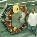
I tested last week my new original Octagon Optima OTLSO Twin Slim LNB with my signal generator to receive 10GHz narrow band from Eshail. As you can see in the Video a clear output but lot of drift after 10min warm up:
https://www.youtube.com/watch?v=vA6CFwVXAY8
So I decided to modify the LNB by removing the cyrstal and then 27 MHz fed through a cap and 47 Ohms resistor to ground:
27MHz reference is mini GPS from Leo Bodnar. Stability is now excellent but problems with quality of the IF signal.
To exclude the generator as a source of error, I tried it with a beacon. No improvement as you can see and hear in the next video:
https://www.youtube.com/watch?v=XFDFM9KHuxQ
Changing the level of the 27MHz signal does not help. Using a BP Filter to clean up the squarewave harmonics didn`t help either.
Anyone here has an idea what the problem is and how can I solve it?
73 and thanks for reading.
Patrick -DH2PA-
DH2PA Patrick sorry I found no mistake. Just for your reference the link to Andy´s document.
Patrick, I had the same problem, using the GPSO from Leo Bodnar. I changed the GPSO frequenz a few Hertz then the effekt was solved.
I am not sure, but I believe that the divider ratio between PLL multiplication and fundamental frequency plays a certain role in this.
Just try it.
73s Robert
Robert you
are my hero of the day. The
frequency changed only 1Hz and it got much better.
Not perfect but much better.
Tnx a lot.
Perfect! ![]()

Perfect!
I think it's not perfect (sorry).
When you've to fudge the reference frequency to an extend that you're (say) 390 Hz off for a proper performance on the RX-frequency . . . something must be fundamentally wrong (again sorry).
So if it works with 27000001 Hz and not with 27000000 Hz all alarm bells must rinkle!
Hello....
My Testsignal with mini GPSDO (Leo B.) 27MHz on LNB
My Testsignal with GPSDO (2xBNC) (Leo B.) 27MHz on LNB
73 Jürgen
And now my test signal with the firmware 1.12 mini GPSDO (Leo B.) 27000000 Hz on LNB
and the necessary settings
Patrick -DH2PA-
I got this answer from Leo regarding my problem:
==========================================================
1) update firmware to version 1.12 http://www.leobodnar.com/files/miniGPSclock-v112.zip
2) Run this configurator http://www.leobodnar.com/files…_configuration-dev112.zip
3) Type 27000000 in Setting frequency field and click "Configure output frequency" button
4) wait until you get GPS clock and click "Save current oscillator correction" - this only needs to be done once. Preferably when correction in ppb has stabilised (device has warmed up internally)
5) Select various Fvco in "DPLL setup" box and see if one of them creates nice stable output. You can play with any of the dropdown boxes but Fvco has the biggest effect. Click "Save and recalibrate PLL"
6) if this does not help, try setting BW to 7 and click "Update".
==========================================================
In my case by 5) and 6), no improvement was obtained
Patrick -DH2PA-
Hello Patrick,
Thank you for your effort. I will
give it a try
VY 73 Jürgen
Remco, you're right, it may not be the perfect solution, but what can be fundamentally wrong?
The fact is, if I use crooked frequencies as the oscillator frequency then the converted signal is clean! In my case, the GPSO runs at 23.589743 MHz, I transpose the transponder band from 10.5 GHz to 1.3 GHz, and I could hear the beacon perfectly clean in CW!
When I fed exactly the 25 MHz at the first test I had exactly this jitter in the NF signal .....
I have no idea what else could be.
73s de Robert
DL5MGD : Yesterday I found a Philips 10 MHz TCXO in the junkbox and made a PLL with other junkbox material. I use a 4017 to divide the 10 MHz and (of course) a LS86 as phase comparator. I've a Ublox NEO-7M which is programmed for 1 MHz Ref-out with an ATTiny13a.
Having the philosophy 'better smartly stolen than badly (re)invented' and (after measuring) finding out that the k of my TCXO was almost 5 Hz/V too, I used your PLL loopfilter values.
The PLL locked immediately. However, on the oscilloscope I still see the jitter of the Ublox on the VCO-voltage. As a try I increased the 100 nF capacitor to 22 uF. The result is that (of course) the PLL takes longer time to lock (it seems to oscillate but damps out in time) and afterwards the Ublox jitter was unvisible here.
Now have to test it in conjunction with my transverter and listen to the audio quality (phase noise) of the whole RX-chain (and compare it with my existing GPSDO).