Chinese RF Power Meter

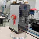
  • I think one of the biggest challenges today is to get a good measurements of our TX power, almost 100% of the OMs heard reports "my power is about / aprox / near / something between x and y Watts" obviously this excludes those few lucky ones with access to professional instruments. In my knowledge the only "amateur" instrument that reaches up to 2.4GHz is the Daiwa CN-801S-II Meter which costs almost the same of a fully ready to go QO-100 station, and the not less expensive and hard to find Bird slugs. Few months ago I got one of this Chinese digital power meter (picture) that claims go from 1MHz to 5GHz, cheap, but so far can not tell if it is functional.


    Their specs:

    Measuring power range: -45~-5 dBm (external RF attenuator can be extended to 80dBm)

    Measurement resolution: 0.1 dBm power

    Measurement frequency range: 1 1MHz-5GHz

    Measured power: 1nW ~ 2W

    Working voltage: 5V DC (direct selection MICRO-USB powered)

    Working current: <50 mA

    Working temperature: -40 ° ~ 65 ° degrees Celsius


    I just found that injecting a 0dBm @ 2.4GHz from a trustable source it displays -19.0dBm so I suppose I will need to input +19dBm in the correction factor to start, so I placed an external 20.4dB attenuator which brings the correction to +39.4dB.

    Using SDR-Console I generated a CW tone on 2.4GHz @ 100% drive and got about 12.5dBm readout (picture), so for me it seems a little exaggerated but it is what is showing. Please let me know if you had made any testing with this type of instrument and the results, also how did you calibrated it?


    Thanks, 73


    Ed PY2RN

  • I have the model that purports to go to 8GHz and as supplied was an absolute pile of crap, When taken to an OP that has the correct gear, at 2.4GHz it was found to be +5dB high at the top end of it's range which is basically around -5dBm


    As you went further down the dBm range I found the error crept higher. The chips on the processor and display board have been scraped to stop one identifying them but I suspect they would be Atmel. Some have reused the detector board at the bottom and done on one of their own processors with A2D on them.


    I did find what I think to be an error on the sampler board where the output resistors were 100 Ohms instead of what I think should be at 10K, the output is basically voltage doubled, with no signal input being around 4.1 Volts going down towards the lower voltage as one puts more signal in.


    I do wonder if a simple diode detector on the output of a 30dB directional coupler would give better results. I have modified mine changing the output resistors and use of a variable pot so that it tracks within 0.5dB from a range of -40input to -10 input at best, not fantastic, but the best I could get. Unless someone can rehash the software in these personnel experience says they are not worth it.


    Sorry if this is not what anyone wants to hear, but just based on my experience.


    Adrian

  • I am using this power meter in combination with a chinese directional coupler. At my work i have the possibility to compare it with (calibrated) network analysers, RF power meter and signal generators.

    In my case I found that this little power meter is accurate if you calibrate it for one frequency.

    Using it on another ham radio band will give complete different and false results.

    No problem, if you want to use it for just 2400 MHz, but of course you have to calibrate it for that frequency.

    With a 40 dB directional coupler and a 10 dB attenuator added my correction factor is 47,2 to measure 10 dBm power and 47,4 for 37 dBm.

    When sweeping the RF generator at qrl from 10 dBm to 37 dBm with 1 dB steps and comparing it to a calibrated HP powermeter i saw no more than 0,5 dB error...so in my opinion it is a cheap and (for ham use) very accurate possibility to do measurements at 2,4 GHz.

  • i agree with PE1RTC, in combination with a R&S generator tested en used. Indeed, only to check deviation/offset per band, eg at 2200, 2300 and 2400 MHz and you have a very useful instrument.


    With a used laptop pwr supply and a DC DC converter and a N chassis connector it helps me with the portsdown and PA for the WB uplink.

  • Link for diy power meter,(AD8318) cheapy build from parts of ebay, BG, alliexpress and case printer with 3d printer. Need calibrate to! Link gifs a lot of info about building and calibrate from all ham Freq til 5.8ghz.

    https://www.rc-cam.com/forum/i…ower-vswr-meter-low-cost/

    Pdf from CQ-DATV https://cq-datv.mobi/DownloadIt.php?id=57&ver=pdf look at pages 20-29

  • I have also ordered this RF Powermeter. Ask the supplier to send me a link for the neccessary software. He send me a link and i come to the download page. But here i must register via Baidu, but all only in Chinese language. Also Google ouer friend don´t help. So i ask Ed PY2RN and he send me the software via Mail. But also he send me a link for a supplier in europe. On this page you will find the software for the RF powermeter as well as the USB drivers and a DLL file. Also you will find the RF power 8000 meter manual in english language there and not in Chinese, as usual.. So have a look to this Page and download the software zip file.

    The link to this page:

    https://www.passion-radio.com/…ter/rf-power8000-926.html     


    73 Joachim

  • I just received the RF 8000 Power meter from China after 2month at the weekend. I also ordered several attenuator from 3dBm to 40dBm.
    This little device is very sensitive (input max around 0dBm) and the best results (low error rate) at -5dBm.
    I was able to test the pluto, the CN0417 and the EP-AB003 step by step but also the entire end-to-end setup. The result was pretty much in line with the projected gain from the supplier, just the EP-AB003 show a bid less gain 14 vs 17 (but this is obviously normal ... ;)

    As I have no calibration tools I mixed the different attenuators (also not calibrated) but it seams all n a range of +- 1dBm. So not precise but for me more then good enough.


    73,Oliver

  • Hello Thomas,

    I cascaded the different attenuator (3) as I started with the Pluto Output of 1dBm followed by -10dBm (1.) attenuator, so -9dBm, followed by the CN0417 (+21,8 dBm) and (2.) attenuator of -20dBm. We are now at -7,2dBm. This signal goes to the EP-AB003 (+14dBm) and the final (3.) attenuator of -9dBm so I measured at the end -2,2dBm.


    1dBm -10dBm +21,8dBm -20dBm +14dBm -9dBm = -2,2dBm (red =attenuator)


    The challenge is to keep the signal in the input range of the amplifiers but below 0dBM for the RF 8000 at the end. The attenuator have only 2W so I have to be careful after the PA.


    73, Oliver

  • Is this right?.

    Hello Thomas,

    I cascaded the different attenuators as I started with the Pluto Output of 1dBm followed by -10dB attenuator, so -9dBm, followed by the CN0417 (+21,8 dBm) and then attenuator of -20dB. We are now at -7,2dBm. This signal goes to the EP-AB003 (+14dBm) and the final (3.) attenuator of -9dB so I measured at the end -2,2dBm.


    1dBm -10dB +21,8dBm -20dB +14dBm -9dB = -2,2dBm (red =attenuator)


    The challenge is to keep the signal in the input range of the amplifiers but below 0dBm for the RF 8000 at the end. The attenuator have only 2W so I have to be careful after the PA.


    73, Oliver

    • Official Post

    Hmm... let me repeat:


    Pluto Output of 1dBm followed by -10dBm (1.) attenuator, so -9dBm

    1.3 mW - 10 dB = 125.9 uW


    followed by the CN0417 (+21,8 dBm)

    125.9 uW + 21.8 dB = 19.1 mW


    and (2.) attenuator of -20dBm.

    19.1 mW - 20 dB = -7.2 dBm / 190.5 uW


    We are now at -7,2dBm.


    Is this right?.

    I think Yes :)


    This signal goes to the EP-AB003 (+14dBm)

    190.5 uW + 14 dB = 6.8 dBm / 4.8 mW


    and the final (3.) attenuator of -9dBm

    4.8 mW - 9dB = -2.2 dBm / 602.6 uW

    so I measured at the end -2,2dBm.

    :thumbup:

    • Official Post

    Interesting would be to measure the EP-AB003 at higher input levels. Now we know that the amplification with -7.2 dBm input is 14 dB which results in 6.8 dBm (* 25.2). With an input of 400 mW / 26 dBm the amplification would be only 10 dB in maximum which results in the maximum power of 4 Watt of this "8 Watt" booster. 500 mW is the maximum input power as I know. But this are guessed values.


    Is anyone willing to measure this WiFi booster ?

  • 500 mW is the maximum input power as I know. But this are guessed values.


    Hello Thomas, 500mW or 27dBM as input for the WiFi booster is much to high. Best range is between 9-15dBm (optimum) or 8mW to 31mW.

    So from my point of view a good result would be at 29dBm or 0,8W behind the Wifi PA ;) . If you trigger the PA with 20dBm (max) you could achieve 34dBm or 2,5W but this is working on the edge. So the truth is somewhere in the middle of 0,8W (proper level) and 2,5W at the highest.

    I believe (measured) 14dB gain is realistic while 17dB is a bid optimistic for that device. That is the reason while I ordered a PA from Bulgaria and use the WiFi PA as driver


    73, Oliver

    • Official Post

    Read TX-only modification on commercial WiFi booster especially #37 ... #43. Johannes did detailed tests with this booster. There are many opinions about this booster, so I think anyone could measure it with different power levels. Mine is very well working with about 400 mW input with a clean signal as I can hear and see on the Goonhilly WebSDR.


    Thanks in advance.